Showing posts with label diagram. Show all posts

Friday, January 10, 2014

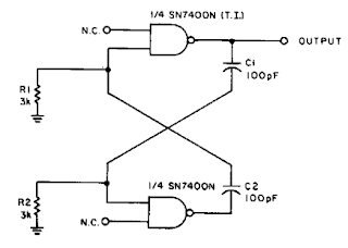
2MHz Square Wave generator Circuit Diagram

With the values shown the circuit generates a 2-MHz symmetrical square wave. Changing capacitors Cl and C2 to 0.01 µ¥ results in a frequency of 500 Hz. For the particular integrated circuits and power supply voltages (5.0 V), the reliable operating range of Rl = R2 is 2 k ohm to 4 k ohm.


2MHz Square Wave generator Circuit Diagram

2MHz Square Wave generator Circuit Diagram

Read More..

Build a Low Ripple Power Supply Circuit Diagram

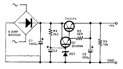
How to build a low ripple power supply circuit diagram. This simple low ripple power supply circuit diagram may be used where a high current is required with a low ripple voltage (such as in a high powered class AB amplifier when high quality reproduction is necessary) , Ql, Q2, and R2 may be regarded as a power darlington transistor.

ZDl and Rl provide a reference voltage at the base of Ql. ZDl should be chosen thus: ZDl = Von-1. C2 can be chosen for the degree of smoothness as its value is effectively multiplied by the combined gains of Q1/Q2, if 100 µF is chosen for C2, assuming minimum hfe for Ql and Q2, C = 100 x 15(Q1) x 25(Q2) = 37,000 µf.


Low Ripple Power Supply Circuit Diagram

Low Ripple Power Supply Circuit Diagram

Read More..

Thursday, January 9, 2014

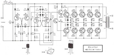
Simple 500W Inverter 12 Volt to 220 Volt Circuit Diagram

This is the Simple 500W Inverter 12 Volt to 220 Volt Circuit Diagram about the the inverter, because like working outdoors, or to backup storage to use when necessary. Most of this is circuit low power, which is not suitable for practical applications. My friends said that he would be about 500 Watt. It is a good size. Use with television receivers and light bulbs as well. When looking for circuit. I get headaches. 

500W Inverter 12 Volt to 220 Volt Circuit Diagram
 
500W Inverter 12 Volt to 220 Volt Circuit Diagram

If you are a beginner or I can not buy expensive good quality circuits. Requires only one transistor. Or if you have free time. I want to build old circuit is alive again. This circuit will accommodate all your needs. It is a simple circuit. The same principle, I take battery voltage 12V to produce a oscillator about 100 Hz and pass to a two frequency divider circuit is only 50HZ. and drive a 10 ampere transformer with 10 x 2N3055 transistor in parallel. 

By a single transistor has 2A, when I use 10 transistors or 5 pairs of drive high current output. The complexity of circuit, but the principle is not it, and it is the number of transistors on a basic, easy to buy. You may be modified 100 watt power inverter To the size of transistors and transformers as well. 

Note:
If you think that This circuit is not good enough. For your work. It is hard to find equipment. You do not have it now. These circuits may be viewed below. It may be appropriate for you.


Source: leksound project

Read More..

Friday, December 27, 2013

Build a Isolated 15V To 2500V Power Supply Circuit Diagram

Build a Isolated 15V To 2500V Power Supply Circuit Diagram. A dc-dc converter using a 74HC04 drives Tl. Tl is a ferrite-core transformer using a Fair-Rite, Inc. P/N 5975000201 (uo + 5000) and has a 7-turn primary and a 25-turn secondary. Kynar, #30 wirewrap wire is used. With Tl, the circuit isolation is good to 2500 V.

Isolated 15V To 2500V Power Supply Circuit Diagram

Isolated 15V To 2500V Power Supply Circuit Diagram

Read More..

Motorcycle Alarm With Transistor Circuit Diagram

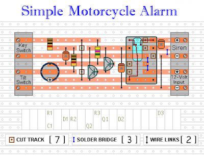
This is a simple Motorcycle Alarm With Transistor Circuit Diagram. Its designed to work at 12-volts. But - if you change the relay for one with a 6-volt coil - itll protect your "Classic Bike". The standby current is virtually zero - so it wont drain your battery.

Motorcycle Alarm With Transistor Circuit Diagram

Motorcycle Alarm With Transistor Circuit Diagram

Any number of normally-open switches may be used. Fit the mercury switches so that they close when the steering is moved or when the bike is lifted off its side-stand or pushed forward off its centre-stand. Use micro-switches to protect removable panels and the lids of panniers etc. While at least one switch remains closed - the siren will sound.

About one minute after all of the switches have been opened again - the alarm will reset. How long it takes to switch off depends on the characteristics of the actual parts youve used. You can adjust the time to suit your requirements by changing the value of C1 and/or R3.

The circuit is designed to use an electronic Siren drawing 300 to 400mA. Its not usually a good idea to use the bikes own Horn because it can be easily located and disconnected. However, if you choose to use the Horn, remember that the alarm relay is too small to carry the necessary current. Connect the coil of a suitably rated relay to the Siren output - and use its contacts to sound the horn.

The circuit board and switches must be protected from the elements. Dampness or condensation will cause malfunction. Without its terminal blocks, the board is small. Ideally, you should try to find a siren with enough spare space inside to accommodate it. Fit a 1-amp in-line fuse as close as possible to the power source. This is Very Important. The fuse is there to protect the wiring - not the circuit board. Instead of using a key-switch you can use a hidden switch; or you could use the normally-closed contacts of a small relay. Wire the relay coil so that its energized while the ignition is on. Then every time you turn the ignition off - the alarm will set itself.

When its not sounding, the circuit uses virtually no current. This should make it useful in other circumstances. For example, powered by dry batteries and with the relay and siren voltages to suit, it could be fitted inside a computer or anything else thats in danger of being picked up and carried away. The low standby current and automatic reset means that for this sort of application an external on/off switch may not be necessary.

When you set the alarm - if one of the switches is closed - the siren will sound. This could cause annoyance late at night. A small modification will allow you to Monitor The State Of The Switches using LEDs. When the LEDs are all off - the switches are all open - and its safe to turn the alarm on.

Veroboard Layout

Veroboard Layout


Read More..

Wednesday, December 25, 2013

Bipolar Power supply for Battery Instruments Circuits Diagram

Bipolar Power supply for Battery Instruments Circuits Diagram. To generate regulated ± 5-V supplies from a pair of dry batteries, the circuit of Fig. 1 is commonly used. In order to give protection from inadvertent reverse connection of a battery, a diode in series with each battery would produce an unacceptable voltage drop. The more effective approach is to fit diodes Dl and D2 as shown in Fig. 2, in parallel with each battery. 

When the supply is switched off, there is the risk of a reverse bias being applied across the regulators, if there is significant inductance or capacitance in the load circuit.Diodes across the regulators prevent damage. When the power supply is switched on, the two switches do not act in unison. There is a probability that one or the other regulators will be latched hard off by the other. To prevent this, D3 and D4 are Zener diodes so that ± 5-V rails are pulled up by the batteries until the regulators establish the correct levels.

Bipolar Power supply for Battery Instruments Circuits Diagram

Bipolar Power supply for Battery Instruments Circuits Diagram

Read More..

Tuesday, December 24, 2013

LM317 VARIABLE POWER SUPPLY Circuit Diagram

A truly timeless circuit. LM317 is a versatile and highly efficient 1.2-37V voltage regulator that can provide up to 1.5A of current with a large heat sink. Its ideal for just about any application. This was my first workbench power supply and I still use it.

 LM317 VARIABLE POWER SUPPLY Circuit Diagram

LM317 VARIABLE POWER SUPPLY Circuit Diagram


Since LM317 is protected against short-circuit, no fuse is necessary. Thanks to automatic thermal shutdown, it will turn off if heating excessively. All in all, a very powerful (and affordable!) package, indeed.

Although LM317 is capable of delivering up to 37V, the circuit pictured here is limited to 25V for the sake of safety and simplicity. Any higher output voltage would require additional components and a larger heat sink.
Make sure that the input voltage is at least a couple of Volts higher than the desired output. Its ok to use a trimmer if youre building a fixed-voltage supply.

Possible uses:
Variable workbench power supply, fixed-voltage supply... Just about any possible application when no more than 1.5A is necessary.
Read More..

Monday, December 23, 2013

Simple Ac To Dc Converter Circuit Diagram

This is simple Ac To Dc converter circuit diagram. By coupling two back-to-back diodes in series with an ac power circuit, a voltage of about 1.4 Vpp can be obtained. This voltage is useful for exciting the primary coil of a small transformer. The voltage induced in the secondary coil can then be rectified and used to power solid-state control circuits. The forward-voltage drop of the diodes is inherently constant and stable over a wide range of ac-circuit power variations. 

The resulting voltage developed across the transformer windings is also free from variation that might be caused by changes in the circuit`s current or voltage. In the circuit, a lamp (LMP-1) is connected to the primary ac input line (Ll and L2) through a pair of inverse-parallel-connected power diodes (Dl and D2). As power flows to the lamp, a drop of about 0.7 V is alternatively developed across each of the diodes. 

This voltage feeds the primary of a small transformer (Tl). T1 can be a small 8- to 500- transistor radio output, etc. This will deliver about 11 Vpp across its secondary winding. LMP1 can be a small 120-V lamp of 5 to 25 W, etc.

Ac To Dc Converter Circuit Diagram

Ac To Dc Converter Circuit Diagram


Simple Ac To Dc Converter Circuit Diagram
Read More..

Atv Jr Transmitter 440Mhz Circuit Diagram

This low-power video transmitter is useful for R/C applications, surveillance, or amateur radio applications. Seven transistors are used in a crystal oscillator-multiplier RF power amplifier chain, and a high-level video modulator. A 9- to 14-Vdc supply is required. Output is 0.4 to 1.2 W, depending on supply voltage. 


Atv Jr Transmitter 440Mhz Circuit Diagram

Atv Jr Transmitter 440Mhz Circuit Diagram

Read More..

Build a 2M 6M Transverter Circuit Diagram

Using the bilateral properties of a balanced mixer this transvertcr will produce 6-m output with 2-m inputs. Y1 is a 90-MHz crystal. Note that the input on 2 m is 143 to 144 MHz for 53 to 54-MHz output. This avoids possibility of extraneous 2-m reception during receive periods. If your radio will not transmit below 144 MHz, then use a 93- or 94-MHz crystal frequency.


2M 6M Transverter Circuit Diagram

2M 6M Transverter Circuit Diagram

Build a 2M 6M Transverter Circuit Diagram
Read More..

Friday, December 20, 2013

Simple 6V lamp Flasher Circuit Diagram


This is a simple lamp flasher circuit diagram.Here you  can use 6V lamp.I have added this for my bike.oh it is great at night I have used blue color bulb.


Note 


# Dont supply over 6V for this circuit 
# Build this circuit on a PCB
Read More..

Voltage Converter Circuit Diagram

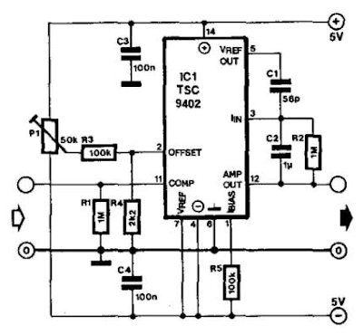
Teledyne Semiconductor`s Type TSC9402 is a versatile IC. Not only can it convert voltage into frequency, but also frequency into voltage. It is thus eminently suitable for use in an add-on unit for measuring frequencies with a multimeter. Only a few additional components are required for this.. Just one calibration point sets the center of the measuring range (or of that part of the range that is used most frequently). 

The frequency-proportional direct voltage at the output (pin 12—amp out) contains interference pulses at levels up to 0.7 V. If these have an adverse effect on the multimeter, they can be suppressed with the aid of a simple RC network. 

The output voltage, U0, is calculated by: tfo=C/rei(Ci + 12 pF) R2fm Because the internal capacitance often has a greater value than the 12 pF taken here, the formula does not yield an absolute value. The circuit has a frequency range of dc to 10 kHz. At 10 kHz, the formula gives a value of 3.4 V. The circuit draws a current of not more than 1 mA.

Voltage Converter Circuit Diagram

Voltage Converter Circuit Diagram

Read More..

Thursday, December 19, 2013

Simple 1 5V Supply For Zn416E Circuits Diagram

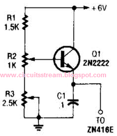
This regulator can be used with a +6-V source to supply ZN416E low-voltage TRF radio-receiver IC the necessary +1.5 V. R3 sets output voltage.


Simple +1.5V Supply For Zn416E Circuits Diagram

Simple +1.5V Supply For Zn416E Circuits Diagram

Read More..

Wednesday, December 18, 2013

Simple split power supply circuit Diagram

This circuit utilizes the quasi-complementary output stage of the popular LM380 audio power IC. The device is internally biased so that with no input the output is held midway between the supply rails Rl, which should be initially set to mid-travel, is used to nullify any inbalance in the output. 

Regulation of Vout depends upon the circuit feeding the LM380, but positive and negative outputs will track accurately irrespective of input regulation and unbalanced loads. 

The free-air dissipation is a little over 1 watt, and so extra cooling: may be required. The device is fully protected and will go into thermal shutdown if its rated dissipation is exceeded. Current limiting occurs if the output current exceeds 1 A. The input voltage should not exceed 20 V.

Simple split power supply circuit Diagram

Simple split power supply circuit Diagram

Read More..

Dual Output dc dc Converter Circuit Diagram

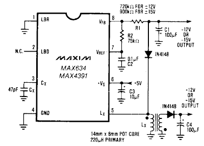
The Dual Output dc-dc Converter Circuit Diagram buck-boost configuration the MAX634 is well suited for dual output dc-dc converters. Only a second winding on the inductor is needed. Typically, this second winding is bifilar-primary and secondary are wound simultaneously using two wires in parallel. 

The inductor core is usually a toroid or a pot core. The negative output voltage is fully regulated by the MAX634. The positive voltage is semi-regulated, and will vary slightly with load changes on either the positive or negative outputs.

Dual Output dc-dc Converter Circuit Diagram

Dual Output dc-dc Converter Circuit Diagram

Read More..

Build a Long Line Ir Drop Voltage Recovery Circuit Diagram

How to Build a Long Line Ir Drop Voltage Recovery Circuit Diagram? This Simple Long Line Ir Drop Voltage Recovery Circuit Diagram provides a unique solution to a common system-level power distribution problem: When the supply voltage to a remote board must traverse a long cable, the voltage at the end of the line sometimes drops to unacceptable levels. 

This + 5-V/ + 5-V converter addresses this by taking the reduced voltage at the end of the supply line and boosting it back to + 5 V. This can be especially useful in remote display devices, such as some point-of-sale (POS) terminals, where several meters of cable could separate the terminal from the readout.

Long Line Ir Drop Voltage Recovery Circuit Diagram

Build a Long Line Ir Drop Voltage Recovery Circuit Diagram

Read More..

Tuesday, December 17, 2013

Regulator current Source Circuit Diagram

The circuit powers the load via the regulator`s input instead of its output. Because the regulator`s output sees constant dummy load R1, it tries to consume a constant amount of current, no matter what the voltage across the actual load really is. Hence, the regulator`s input serves as a constant-current source for the actual load. 

Power the circuit with any one of the commonly available ± 15 or ±12 V supplies. The voltage dropped across the regulator and dummy load decreased the total compliance voltage of the~circuit. You set the load`s current with Rl. The current equals 1.25 A/`J x Rl.


Regulator current Source Circuit Diagram

Regulator current Source Circuit Diagram


Regulator current Source Circuit Diagram
Read More..

Thursday, October 10, 2013

PRECISION POWER REGULATOR ELECTRONIC DIAGRAM


PRECISION POWER REGULATOR ELECTRONIC DIAGRAM

A precision voltage source is quite easy, except when the voltage should be consistent over wide range of ambient temperature. This requirement might be needed in high precision measurement system environment. For example, to provide reference voltage in analog to digital conversion.
Read More..

Wednesday, October 9, 2013

1992 Chrysler Dynasty Wiring Diagram

1992 Chrysler Dynasty Wiring Diagram

The Part of 1992 Chrysler Dynasty Wiring Diagram:ground splice, front door, heated mirror, left motor
inside, splice, feed, splice, gray, deck lid pull, yellow wire, ride wire, instrument panel
Read More..

Tuesday, October 8, 2013

12 V AUDIO AMPLIFIER WITH TRANSISTOR ELECTRONIC DIAGRAM

12 V AUDIO AMPLIFIER WITH TRANSISTOR ELECTRONIC DIAGRAM

In use, R9 should be carefully adjusted to provide minimal audible signal cross-over distortion consistent with minimal measured quiescent current consumption; a good compromise is to set the quiescent current at about 10-15 mA.To measure this current, wire a DC current meter temporarily in series with the collector of Q3.

List Component

  • P1_____________10K Log.Potentiometer
  • R1,R2__________33K 1/4W Resistors
  • R3_____________33R 1/4W Resistor
  • R4_____________15K 1/4W Resistor
  • R5,R6___________1K 1/4W Resistors
  • R7____________680R 1/4W Resistor
  • R8____________120R 1/2W Resistor
  • R9____________100R 1/2W Trimmer Cermet
  • C1,C2__________10µF 63V Electrolytic Capacitors
  • C3____________100µF 25V Electrolytic Capacitor
  • C4,C7_________470µF 25V Electrolytic Capacitors
  • C5_____________47pF 63V Ceramic Capacitor
  • C6____________220nF 63V Polyester Capacitor
  • C8___________1000µF 25V Electrolytic Capacitor
  • D1___________1N4148 75V 150mA Diode
  • Q1____________BC560C 45V 100mA PNP Low noise High gain Transistor
  • Q2____________BC337 45V 800mA NPN Transistor
  • Q3____________TIP31A 60V 4A NPN Transistor
  • Q4 ___________TIP32A 60V 4A PNP Transistor
  • SW1___________SPST switch
Read More..