
Friday, December 27, 2013
Build a Isolated 15V To 2500V Power Supply Circuit Diagram

Ground free DVM Module Supply from 5 V
Ground-free DVM Module Supply from 5 V Circuit Diagram :

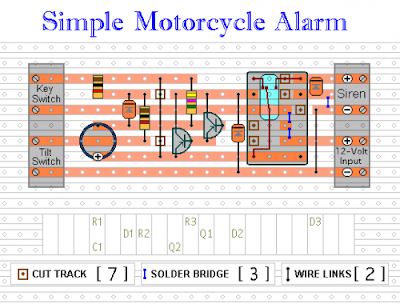
Motorcycle Alarm With Transistor Circuit Diagram

Veroboard Layout
Thursday, December 26, 2013
Latch Up Alarm Using Opto Coupler
Latch-Up Alarm Using Opto-Coupler Circuit Diagram

It is unnecessary for the customer to stop the use
There are some mobile phones which are having many advanced features and so their cost is high. However, you can find several cheap mobile phones available in the UK market online mobile phone shops give you the latest brands from the prominent manufacturers at a very competitive price offer. The worst of it is that others use it to send objective answers to those in the examination hall, which may not be correct at the end of the day. This can end the students career if caught, as exam malpractice is a punishable offense.
In the end, I had to fork out a sum of $200 to clean up the mould and to get the mobile phone functioning again some 3 months later, because by the time it was repaired, I was back in Australia and had to get a friend to retrieve it for me.
Now, the lesson of this experience is simple - Read the fine print of your warranty that comes with every purchase of your mobile phone.Just because what you buy is an established brand, never ever assume that its design is built to keep out the moisture or that it would not become mouldy inside, not even if it is a Sony. I was told it was standard policy to treat mouldy conditions within the mobile phone as a result of improper use of the mobile phone, rendering any warranty void.
While the mobile phone was a newer model, and I had always considered it an important part of my professional tools, there was never any case of mis-use of the mobile phone that could have allowed water to seep inside the mobile phone. If there was any mould, it would only have been the change of weather from the country of purchase and the country of use.
Let my experience be your guide, and pay attention to the fine print of your warranty so that you are sure whether mouldy conditions are covered under the warranty especially if you are going to use a mobile phone purchased overseas where there are different climatic conditions.
Avoid buying a lemon when you are shopping for a newer mobile phone. Visit your local Australian and New Zealand mobile phones online store Aussie Mobile Phones Store [http://aussie-mobilephones.reviewadvisors.info] for free resources and to view the latest in mobile phones for the Australian and New Zealand region. Updated daily, the website has a vast array of mobile phones on offer for the discerning user, and provides an online shopping experience with a difference.
Secondary school is a term used to describe an educational institution where the final stage of schooling, known as secondary education and usually compulsory up to a specified age, takes place. It follows elementary or primary education, and may be followed by university (tertiary) education.
Cat and Dog Repeller

3V Low Battery Voltage Flasher

The electronic circuit draws only 1ua of current in standby mode and jumps to only 20ua when flashing, so it can safely be included without depleting the battery energy. A voltage detector IC from Panasonic (Microchip also makes similar devices) is used to monitor the battery voltage. The device’s open drain output swings low, when the battery voltage is below 2.4 to 2.5 volts. This action turns on the two transistor oscillator circuit, which drives the LED with short current pulses lasting only 2ms.
Wednesday, December 25, 2013
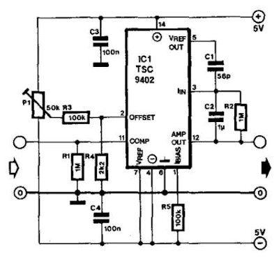
Bass and Treble Controller Audio Equalizer Circuit
Circuit Diagram of Bass & Treble Controller- Audio Equalizer:
 |
| Fig: Audio equalizer circuit for Bass, Treble control |
Jogging Timer
This circuit was developed since a number of visitors of this website requested a timer capable of emitting a beep after one, two, three minutes and so on, for jogging purposes. As shown in the circuit diagram, SW1 is a 1 pole 9 ways Rotary Switch. Setting the switch in position 1, the Piezo sounder emits three short beeps every minute. In position 2 the same thing happens after a 2 minutes delay, and so on, reaching a maximum interval of 9 minutes in position 9.
Circuit diagram:
Parts:
R1_____________47K 1/4W Resistor
R2_____________10M 1/4W Resistor
R3______________1M 1/4W Resistor
R4_____________12K 1/4W Resistor (see notes)
C1,C3__________10µF 25V Electrolytic Capacitors
C2____________100nF 63V Polyester Capacitor
D1___________1N4148 75V 150mA Diode
IC1____________4093 Quad 2 input Schmitt NAND Gate IC
IC2____________4060 14 stage ripple counter and oscillator IC
IC3____________4017 Decade counter with 10 decoded outputs IC
Q1____________BC337 45V 800mA NPN Transistor
SW1___________1 pole 9 ways Rotary Switch (see notes)
SW2___________SPST Slider Switch
BZ1___________Piezo sounder (incorporating 3KHz oscillator)
B1____________3V Battery (two 1.5V AA or AAA cells in series etc.)
Notes:
- Needing only one time set, rotary switch can be replaced by an hard-wired link.
- A DIP-Switch can be used in place of the rotary type. Please pay attention to use only one switch at a time, or the device could be damaged.
- Varying R4 from 10K to 15K you can obtain more or less than three short beeps after the preset time delay.
- To obtain a one-second beep only, after the preset time delay, disconnect pin 9 of IC1C from pin 9 of IC2 and connect it to pin 8 of IC1C.
Bipolar Power supply for Battery Instruments Circuits Diagram

DC or AC Voltage Indicator
This circuit is not a novelty, but it proved so useful, simple and cheap that it is worth building. When the positive (Red) probe is connected to a DC positive voltage and the Black probe to the negative, the Red LED will illuminate. Reversing polarities the Green LED will illuminate. Connecting the probes to an AC source both LEDs will go on.
The bulb limits the LEDs current to 40mA @ 220V AC and its filament starts illuminating from about 30V, shining more brightly as voltage increases. Therefore, due to the bulb filament behavior, any voltage in the 1.8 to 230V range can be detected without changing component values.
Circuit diagram:

Parts:
P1 = Red Probe
P2 = Black Probe
D1 = 5 or 3mm. Red LED
D2 = 5 or 3mm. Green LED
LP = 1220V 6W Filament Lamp Bulb
Note:
- A two colors LED (Red and Green) can be used in place of D1 & D2.
Tuesday, December 24, 2013
Laser Power Supply

Parts |
Notes
|
Automatic Emergency Light
Automatic Emergency Light Circuit diagram:

LM317 VARIABLE POWER SUPPLY Circuit Diagram

Since LM317 is protected against short-circuit, no fuse is necessary. Thanks to automatic thermal shutdown, it will turn off if heating excessively. All in all, a very powerful (and affordable!) package, indeed.
Although LM317 is capable of delivering up to 37V, the circuit pictured here is limited to 25V for the sake of safety and simplicity. Any higher output voltage would require additional components and a larger heat sink.
Make sure that the input voltage is at least a couple of Volts higher than the desired output. Its ok to use a trimmer if youre building a fixed-voltage supply.
Variable workbench power supply, fixed-voltage supply... Just about any possible application when no more than 1.5A is necessary.
Monday, December 23, 2013
Precision Headphone Amplifier


Simple Ac To Dc Converter Circuit Diagram

Simple Ac To Dc Converter Circuit Diagram
Atv Jr Transmitter 440Mhz Circuit Diagram
Atv Jr Transmitter 440Mhz Circuit Diagram

Build a 2M 6M Transverter Circuit Diagram
2M 6M Transverter Circuit Diagram

Build a 2M 6M Transverter Circuit Diagram
Sunday, December 22, 2013
Fixed Voltage Power Supply
The fixed voltage power supply is useful in applications where an adjustable output is not required. This supply is simple, but very flexable as the voltage it outputs is dependant only on the regulator and transformer you choose. The maximum output current is 1.5A.
Fixed Voltage Power Supply Circuits diagram :

Parts :
Part Total Description
C1 1 2200uF 35V Electrolytic Capacitor
C2, C4 2 0.1uF Ceramic Disc Capacitor
C3 3 10uF 35V Electrolytic Capacitor
D1, D2 1 1N4007 Silicon Diode
BR1 1 2A 30V Bridge Rectifier
U1 1 Regulator (See Notes)
T1 1 Transformer (See Notes)
S1 1 SPST 2 Amp Switch
F1 1 2A 250V Fuse and Holder
Misc 1 Heatsink For U1, Line Cord, Case, Wire
Notes :
- Since this project operates from 120 (or 220, or 240, etc.) volts AC, it MUST be built inside a case.
- U1 will reauire a heatsink.
- You will need to choose T1 and U1 to match the voltage you want. Use the table below as a reference.
MD Catridge Preamplifier
MD Catridge Preamplifier Circuit diagram:

12V Speed Controller Dimmer


Connection diagram:


Halogen lamps:
While the circuit can dim 12V halogen lamps, we should point out that dimming halogen lamps is very wasteful. In situations where you need dimmable 12V lamps, you will be much better off substituting 12V LED lamps which are now readily available in standard bayonet, miniature Edison screw (MES) and MR16 halogen bases. Not only are these LED replacement lamps much more efficient than halogen lamps, they do not get anywhere near as hot and will also last a great deal longer.
Saturday, December 21, 2013
Musical Bell

This circuits uses very few component and gives melody sound. It uses 3 terminal IC UM66 and can be build small enough to be placed inside a greeting card and operated off a single 3V flat button cell.
There is not much to the circuit. The UM66 is connected to its supply and its output fed to a transistor for amplification. Any common speaker can be used or a “flat” piezoelectric tweeter like the one found in alarm wrist watches. If you use the piezo, then it can be connected directly between the output pin 1 and ground pin 3 without the transistor.
The UM66 looks like a transistor with 3 terminals. It is complete miniature tone generator with a tune. Now they come with wide variety of different tunes.
For amplification we have used a NPN transistor which is BC548. Here BC548 makes a common emitter circuit. For limiting the base current we have used a resistance of 220 Ohms so that transistor will not get damaged by excess current.

Circuit Diagram of Musical Bell
PROCEDURE :
1. Draw circuit diagram on ply board and make hole with compass or broader for component pin insertion.
2. Identify emitter base collector of transistor and pin no. of IC UM66
3. Solder all parts according to the circuit. You will need soldering iron, Soldering flux and flexible wire.
4. Make sure all points are well soldered according to the Circuit Diagram and no dry solders. Wrong connection of IC may heat up and get damage.
5. After loading battery power ON the circuit. Now you can check the function of the project.
500W Low Cost 12V to 220V Inverter

The basic formula is P=VI and between input output of the transformer we have Power input = Power output
For example if we want a 220W output at 220V then we need 1A at the output. Then at the input we must have at least 18.3V at 12V because: 12V*18.3 = 220v*1
So you have to wind the step up transformer 12v to 220v but input winding must be capable to bear 20A.
Set Reset Flip Flop
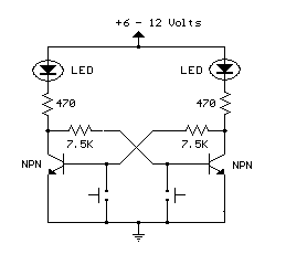 |
| Set - Reset Flip Flop Circuit Diagram |
- Source
- Bowdens Hobby Circuits
Voltage Inverter Using Switch Mode Regulator


Friday, December 20, 2013
Simple 6V lamp Flasher Circuit Diagram

This is a simple lamp flasher circuit diagram.Here you can use 6V lamp.I have added this for my bike.oh it is great at night I have used blue color bulb.

# Dont supply over 6V for this circuit
# Build this circuit on a PCB
Voltage Converter Circuit Diagram
230V Led Flasher Circuit using DIAC
230V Mains Power Indicator LED Flasher Circuit Diagram
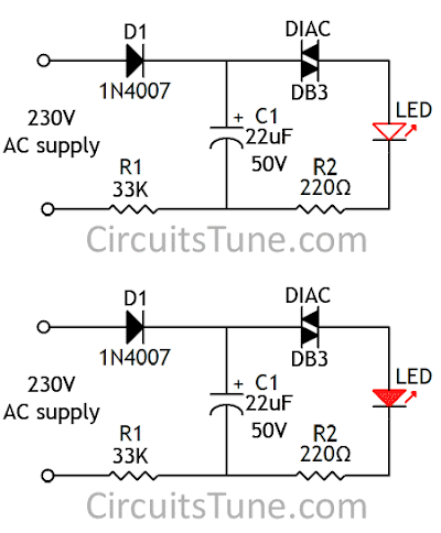 |
| Fig: Circuit Diagram of 230V Led Flasher |
When mains is connect to the circuit, the Capacitor(C1) starts charging through Diode(D1) and Resistor(R1). When the voltage on the capacitor reached the DIAC’s threshold voltage, the DIAC get turn on. And LED gets Lights(flash). At the same time Capacitor(C1) goes discharges and breakover voltage of DIAC also decrease and LED turns OFF. The on off time of the LED depends on the value of Capacitor(C1) and Resistor(R1).
10W Audio Amplifier With Bass Boost

P1_________________22K Log.Potentiometer (Dual-gang for stereo)
P2_________________100K Log.Potentiometer (Dual-gang for stereo)
R1_________________820R 1/4W Resistor
R2,R4,R8___________4K7 1/4W Resistors
R3_________________500R 1/2W Trimmer Cermet
R5_________________82K 1/4W Resistor
R6,R7______________47K 1/4W Resistors
R9_________________10R 1/2W Resistor
R10________________R22 4W Resistor (wirewound)
C1,C8______________470nF 63V Polyester Capacitor
C2,C5______________100µF 25V Electrolytic Capacitors
C3,C4______________470µF 25V Electrolytic Capacitors
C6_________________47pF 63V Ceramic or Polystyrene Capacitor
C7_________________10nF 63V Polyester Capacitor
C9_________________100nF 63V Polyester Capacitor
D1_________________1N4148 75V 150mA Diode
IC1_________________NE5532 Low noise Dual Op-amp
Q1_________________BC547B 45V 100mA NPN Transistor
Q2_________________BC557B 45V 100mA PNP Transistor
Q3_________________TIP42A 60V 6A PNP Transistor
Q4_________________TIP41A 60V 6A NPN Transistor
J1__________________RCA audio input socket
Power Supply Circuit diagram:

R11______________1K5 1/4W Resistor
C10,C11__________4700µF 25V Electrolytic Capacitors
D2_______________100V 4A Diode bridge
D3_______________5mm. Red LED
T1_______________220V Primary, 12 + 12V Secondary 24-30VA Mains transformer
PL1______________Male Mains plug
SW1______________SPST Mains switch
Notes:
- Can be directly connected to CD players, tuners and tape recorders.
- Schematic shows left channel only, but C3, C4, IC1 and the power supply are common to both channels.
- Numbers in parentheses show IC1 right channel pin connections.
- A log type for P2 will ensure a more linear regulation of bass-boost.
- Do not exceed 18 + 18V supply.
- Q3 and Q4 must be mounted on heatsink.
- D1 must be in thermal contact with Q1.
- Quiescent current (best measured with an Avo-meter in series with Q3 Emitter) is not critical.
- Set the volume control to the minimum and R3 to its minimum resistance.
- Power-on the circuit and adjust R3 to read a current drawing of about 20 to 25mA.
- Wait about 15 minutes, watch if the current is varying and readjust if necessary.
- A correct grounding is very important to eliminate hum and ground loops. Connect to the same point the ground sides of J1, P1, C2, C3 &C4. Connect C9 to the output ground.
- Then connect separately the input and output grounds to the power supply ground.
Output power:
10 Watt RMS into 8 Ohm (1KHz sinewave)
Sensitivity:
115 to 180mV input for 10W output (depending on P2 control position)
Frequency response:
See Comments above
Total harmonic distortion @ 1KHz:
0.1W 0.009% 1W 0.004% 10W 0.005%
Total harmonic distortion @ 100Hz:
0.1W 0.009% 1W 0.007% 10W 0.012%
Total harmonic distortion @ 10KHz:
0.1W 0.056% 1W 0.01% 10W 0.018%
Total harmonic distortion @ 100Hz and full boost:
1W 0.015% 10W 0.03%
Max. bass-boost referred to 1KHz:
400Hz = +5dB; 200Hz = +7.3dB; 100Hz = +12dB; 50Hz = +16.4dB; 30Hz = +13.3dB
Unconditionally stable on capacitive loads
Thursday, December 19, 2013
Car Boot Light Warning

Simple 1 5V Supply For Zn416E Circuits Diagram
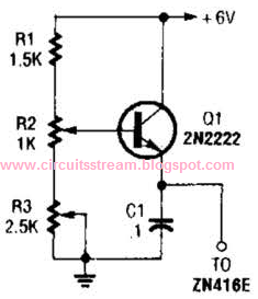
Simple +1.5V Supply For Zn416E Circuits Diagram
Photodiode Alarm
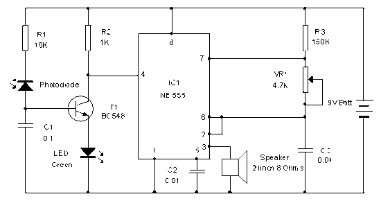
The NPN transistor T1 conducts and takes the reset pin 4 of IC1 to ground potential. IC1 is wired as an Astable oscillator using the components R3, VR1 and C3. The Astable operates only when its resent pin becomes high. When the Laser / IR beam breaks, current thorough the Photodiode ceases and T1 turns off. The collector voltage of T1 then goes high and enables IC1. The output pulses from IC1 drives the speaker and alarm tone will be generated.
Photo-Diode Alarm Circuit
IR Transmitter Circuit

A simple IR transmitter circuit is given which uses Continuous IR rays. The transmitter can emit IR rays up to 5 meters if the IR LEDs are enclosed in black tubes.
Wednesday, December 18, 2013
Simple split power supply circuit Diagram

Dual Output dc dc Converter Circuit Diagram
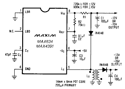
Build a Long Line Ir Drop Voltage Recovery Circuit Diagram

200w Audio Power Amplifier
200W Audio Power Amplifier Circuit Diagram :

Doing so it is necessary to mount the transistors and the IC’s insulated (with mica washes and plastic nipple). Please make sure before first operation that the transistors and the IC’s really do not have any electrical connection towards the cooling plate! The transistors have to be placed plane and firmly onto the cooling element! It is of extraordinary importance with this high-power amplifier that there is a considerable heat dissipation. The already mounted cooling element should be situated in a well ventilated case.
The PSU should be sufficiently powerful, power consumption of the amplifier may increase up to 5A. In case of using an unstabilised power supply. It is advisable to place a transformer of max 28V.
The amplifier will the show approx. 120W at a 4-Ohm loudspeaker, for it no-load voltage of the power supply will not be to high. If it is desired to use complete power, it is necessary to place a stabilised power supply with approx. 36V 5A. No-load voltage should not pass over 44V!
The cables leading the current supply and to the loudspeakers should have at least a cross section of min. 1.5 mm^2. The connected loudspeaker have to be equiped according to the high output power and should not have a lower impedance as 4 Ohm! With lower connection impedance and short circuit within the loudspeaker wiring, the transistors will be destructed.
The amplifier has an input sensitivity of approx. 500 … 800 mV. Therefore, it is possibile to connect directly at the amplifier tape decks, tuners, etc. In case there are connected signal sources with lower output voltage, it is necessary to pre-connect a preamplifier. Then it will alse be posible to connect microphones, etc.
200W audio amplifier PCB :

Parts List :
IC1, IC2 = 2 IC’s TDA2030
T1, T3 = 2 transistors KT818 or BD708
T2, T4 = 2 transistors KT819 or BD705
C1, C2, C3, C4, C7 = 5 capacitors 150 nF
C5 = 1 elca 10uF 63V
C8 – 1 capacitor 1.8 nF
R1, R7, R9 = 3 resistances 100K
R2, R3, R10, R11 = 4 resistances 2.2 Ohm
R4, R5 = 2 res. 2K
R6, R8 = 2 res. 1 Ohm
R12, R13 = 2 res. 2 res. 3.3K
D1…D4 = 1N4001, 1N4002, 1N4003
1 PCB board approx 56×51 mm
Tuesday, December 17, 2013
Laser Level Detector


Stepper Motor Circuit with IC 4027
This stepper controller circuit shown here can used to control the unipolar stepper motor,which has 4 coils . The stepper controller circuit can drive for a motor current of up to about 500 mAmp/Winding by suitable heat sinks for the SL-100. directsinks In higher currents power transistors seem 2N3055 can be used as darlington pair along with SL-100. All diodes are used to protect back current the transistor from transients.
Stepper Motor Circuit with IC 4027 Circuit diagram :

Remark.
- You may be able to substitute any standard (2N3055) power transistor for Q1-Q4 or get IC type UL to modify for transistor.
- Every time in move the motor put signal the STEP line is pulsed, the motor moves one step.
- Switch S1 for changes the motors direction
Regulator current Source Circuit Diagram
