Showing posts with label alarm. Show all posts

Friday, December 27, 2013

Motorcycle Alarm With Transistor Circuit Diagram

This is a simple Motorcycle Alarm With Transistor Circuit Diagram. Its designed to work at 12-volts. But - if you change the relay for one with a 6-volt coil - itll protect your "Classic Bike". The standby current is virtually zero - so it wont drain your battery.

Motorcycle Alarm With Transistor Circuit Diagram

Motorcycle Alarm With Transistor Circuit Diagram

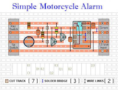
Any number of normally-open switches may be used. Fit the mercury switches so that they close when the steering is moved or when the bike is lifted off its side-stand or pushed forward off its centre-stand. Use micro-switches to protect removable panels and the lids of panniers etc. While at least one switch remains closed - the siren will sound.

About one minute after all of the switches have been opened again - the alarm will reset. How long it takes to switch off depends on the characteristics of the actual parts youve used. You can adjust the time to suit your requirements by changing the value of C1 and/or R3.

The circuit is designed to use an electronic Siren drawing 300 to 400mA. Its not usually a good idea to use the bikes own Horn because it can be easily located and disconnected. However, if you choose to use the Horn, remember that the alarm relay is too small to carry the necessary current. Connect the coil of a suitably rated relay to the Siren output - and use its contacts to sound the horn.

The circuit board and switches must be protected from the elements. Dampness or condensation will cause malfunction. Without its terminal blocks, the board is small. Ideally, you should try to find a siren with enough spare space inside to accommodate it. Fit a 1-amp in-line fuse as close as possible to the power source. This is Very Important. The fuse is there to protect the wiring - not the circuit board. Instead of using a key-switch you can use a hidden switch; or you could use the normally-closed contacts of a small relay. Wire the relay coil so that its energized while the ignition is on. Then every time you turn the ignition off - the alarm will set itself.

When its not sounding, the circuit uses virtually no current. This should make it useful in other circumstances. For example, powered by dry batteries and with the relay and siren voltages to suit, it could be fitted inside a computer or anything else thats in danger of being picked up and carried away. The low standby current and automatic reset means that for this sort of application an external on/off switch may not be necessary.

When you set the alarm - if one of the switches is closed - the siren will sound. This could cause annoyance late at night. A small modification will allow you to Monitor The State Of The Switches using LEDs. When the LEDs are all off - the switches are all open - and its safe to turn the alarm on.

Veroboard Layout
Veroboard Layout


Read More..

Thursday, December 26, 2013

Latch Up Alarm Using Opto Coupler

The latch-up alarm described here is based on single IC NE555, configured as an astable multivibrator. The timing components are selected such that the oscillation frequency of the multivibrator lies within the audio range. Instead of a flip-flop stage, an opto-coupler (MCT2E) is used for latching of the alarm.  Under normal condition, pin 4 of IC1 is pulled to ground via resistor R2, and its output at pin 3 is held  ‘low’. When switch S1 is pressed momentarily, transistor T1 conducts to bring reset pin 4 of 555 to logic  ‘high’. As a result, IC1 is activated and the alarm starts to sound.
 
Latch-Up Alarm Using Opto-Coupler Circuit Diagram

Latch-Up Alarm Using Opto-Coupler Circuit-Diagram

 
Simultaneously, the LED inside opto-coupler glows and the phototransistor conducts. As a result, trigger transistor T1 gets base bias via phototransistor and resistor R6. The alarm sounds continuously until reset switch S2 is pressed. When switch S2 is pressed, transistor T1 is switched  ‘off’ to bring pin 4 of IC1 to logic ‘low’ and the alarm is disabled.


Source:   http://www.ecircuitslab.com/2012/01/latch-up-alarm-using-opto-coupler.html


Read More..

Thursday, December 19, 2013

Photodiode Alarm

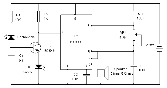
This Photodiode based Alarm can be used to give a warning alarm when someone passes through a protected area. The circuit is kept standby through a laser beam or IR beam focused on to the Photodiode. When the beam path breaks, alarm will be triggered. The circuit uses a PN Photodiode in the reverse bias mode to detect light intensity. In the presence of Laser / IR rays, the Photodiode conducts and provides base bias to T1.

The NPN transistor T1 conducts and takes the reset pin 4 of IC1 to ground potential. IC1 is wired as an Astable oscillator using the components R3, VR1 and C3. The Astable operates only when its resent pin becomes high. When the Laser / IR beam breaks, current thorough the Photodiode ceases and T1 turns off. The collector voltage of T1 then goes high and enables IC1. The output pulses from IC1 drives the speaker and alarm tone will be generated.

Photo-Diode Alarm Circuit

Circuit Project: Photodiode Alarm circuit

IR Transmitter Circuit

Circuit Project: Photodiode Alarm circuit

A simple IR transmitter circuit is given which uses Continuous IR rays. The transmitter can emit IR rays up to 5 meters if the IR LEDs are enclosed in black tubes.
Read More..

Monday, September 23, 2013

Infrared Proximity Detector Alarm

This circuit can be built from readily available low-cost components, some of which may even be hiding in your junk-box! The indicated value of 22 Ω for resistor R1 causes an average current of about 65mA through infrared emitter D1. Because the IRED is pulsed at a duty factor of about 50% through the action of T1 and IC1, a peak current of 128mA flows during every half cycle. This may seem a lot but in fact is well within the safe specification of the LD274. The LM567 PLL IC is configured to supply a switching frequency of about 20 kHz. When the infrared beam emitted by D1 is reflected by a nearby object, IC1, through receiver diode D2 and transistor T2, receives the recovered 20 kHz signal at its input, pin 3.

Infrared Proximity Detector Alarm Circuit DiagramBecause the ‘567 PLL is then locked, the IC output (pin 8), drops low, triggering the 555 chip in monostable mode (IC2) and so causing acoustic actuator Bz1 to sound. The monostable remains on as long as the reflected signal is being received. Because of the presence of T3, capacitor C5 is allowed to charge only when no signal is being received. In that condition, the 555 is turned off automatically after a time determined by R9-C5. Using the component values shown, this will be about 5 seconds. Obviously D1 and D2 should be mounted such that the latter can only pick up reflected infrared light.

The choice of the two infrared components used in this circuit will be uncritical but they must be ‘band’ compatible, i.e., generate (D1) and respond to (D2) the same wavelength. The operating point of the receiver input circuit is rather dependent on ambient day-light levels and the value of R4 may need to be adjusted a little to ensure a voltage of between 1.5 V and 4 V on the collector of T1 when no signal is being received. Some dc buzzers cause a lot of back-emf so it may be necessary to insert a diode in series with the output of IC1. If necessary, this diode should preferably be a Schottky type because of the inherent low voltage drop of about 0.4 V as opposed to 0.65 V for a typical small-signal silicon diode.
Read More..

Tuesday, May 14, 2013

Low cost fire alarm circuit


When there is a fire breakout in the room the temperature increases.This ultra compact and low cost fire alarm senses fire breakout based on this fact.
Transistor BC177 (Q1) is used as the fire sensor here.When the temperature increases the leakage current of this transistor also increases.The circuit is designed so that when there is an increase in the leakage current of Q1 ,transistor Q2 will get biased.As a result when there is a fire breakout the transistor Q2 will be on.The emitter of Q2 (BC 108)is connected to the base of Q3(AC 128).So when Q2 is ON Q3 will be also ON.The transistor Q3 drives the relay which is used to drive the load ie,light,bell,horn etc as an indication of the fire.The diode D1 is used as a free wheeling diode to protect it from back EMF generated when relay is switche

Notes.

* The Preset R1 can be used to desired temperature level for setting the alarm ON.
* This is not a latching alarm,ie;when the temperature in the vicinity of the sensor decreases below the set point the alarm stops.
* The circuit can be powered using a 9V battery or a 9V battery eliminator.
* All capacitors are electrolytic and must be rated at least 10V.
* The load can be connected through the C,NC,NO points of the relay according to your need.
* The calibration can be done using a soldering iron,and a thermo meter.Switch ON the power supply.Keep the tip of soldering iron near to the Q1.Same time also keep the thermometer close to it.When the temperature reaches your desired value adjust R1 so that relay gets ON.Done!

Read More..

Monday, April 8, 2013

Pyro Electric Fire Alarm

Here is an ultra-sensitive fire sensor that exploits the direct piezoelectric property of an ordinary piezo element to detect fire. The lead zirconate titanate crystals in the piezo element have the property to deform and generate an electric gate protected p-channel MOSFETs in the inputs. It has high speed of performance and low input current requirements.There are two inputs—the non-inverting input (pin 3) connected to the piezo element through diode D7 (OA71) that carries the voltage signal from the piezo element and the inverting input (pin 2) that gets a preset voltage momentarily changes the voltage level at pin 3 of IC1 and its output swings high.

Transistor T1 conducts taking the reset pin 12 of IC2 to ground. IC2 is now enabled and starts oscillating. With the shown values of the oscillating components C3 (0.22μ) and R6 potential when heated, thus converting the piezo element into a heat sensor. The circuit described here is very sensitive. It gives a warning alarm if the room temperature increases more than 10°C. The entire circuit has two sections—the sensor and the power supply section.


Pyro electric fire alarm Circuit diagram Fig. 1: Pyroelectric fire sensor Circuit Daigram

Sensor side circuit. Fig. 1 shows the fire sensor circuit. The front end of the circuit has a sensitive signal amplifier built around IC1 (CA3130). It gives a high output when temperature near the piezo element increases. IC CA3130 is a CMOS operational amplifier with gate protected p-channel MOSFETs in the inputs. It has high speed of performance and low input current requirements. There are two inputs—the non-inverting input (pin 3) connected to the piezo element through diode D7 (OA71) that carries the voltage signal from the piezo element and the inverting input (pin 2) that gets a preset voltage through VR1.

Power supply with battery backup Fig. 2: Power supply with battery backup

By adjusting VR1,it is easy to set the reference voltage level at pin 2. In normal condition, IC1 gives a low output and the remaining circuitry is in a standby state. Capacitor C2 keeps the non-inverting input of IC1 stable,so that even a slight change in voltage level in the inputs can change the output to high. Normally, IC1 gives a low output, keeping transistor T1 non-conducting. Reseting pin 12 of IC2 (CD4060) connected to the collector of transistor T1 gets a high voltage through R5 and IC2 remains disabled. When the piezo element gets heat from fire, asymmetry in its crystals causes a potential change, enabling capacitor C2 to discharge.

It (1M), the first output (Q3) turns high after a few seconds and a red LED2 starts flashing. If heat near the piezo persists, Q7 (pin 14) output of IC2 becomes high after one minute, and the alarm starts beeping. If heat continues, Q9 (pin 15) turns high after four minutes and turns on the relay driver transistor T2. At the same time, diode D8 conducts and IC2 stops oscillating and toggles. The solenoid pump connected to the N/O (normally opened) contact of the relay starts spraying the fire-ceasing foam or water to the possible sites of fire. Power supply circuit. Powe supply section (Fig. 2) comprises a 0-12V, 1A step-down transformer with a standard full-wave rectifier formed by D1 through D4 and filter capacitor C1. A battery backup is provided if the mains supply is cut-offb due to short-circuit and fire. A 12V, 4.5Ah rechargeable battery is used for backup to give sufficient current to the solenoid pump. When mains power is available, diode D5 forward biases.

It provides power to the circuit and also charges the battery through resistor R2, and it limits the charging current to 120 mA. When power fails, diode D5 reverse biases and diode D6 forward biases, giving instant backup to the circuit. LED1 indicates the availability of mains power. Assemble the circuit on a generalpurpose PCB and enclose it in a suitable case. Connect the piezo element to the circuit using a thin insulated wire. Glue the flat side of the piezo element on a 30×30cm aluminium sheet to increase its sensitivity. Fix the sheet with the piezo sensor to the site where protection is needed. The remaining circuit can be fixed at a suitable place. If only the alarm generator is needed, omit the relay driver section.

Author :D. Mohan Kumar :Copyright: EFY

Read More..