Showing posts with label with. Show all posts

Friday, December 27, 2013

Motorcycle Alarm With Transistor Circuit Diagram

This is a simple Motorcycle Alarm With Transistor Circuit Diagram. Its designed to work at 12-volts. But - if you change the relay for one with a 6-volt coil - itll protect your "Classic Bike". The standby current is virtually zero - so it wont drain your battery.

Motorcycle Alarm With Transistor Circuit Diagram

Motorcycle Alarm With Transistor Circuit Diagram

Any number of normally-open switches may be used. Fit the mercury switches so that they close when the steering is moved or when the bike is lifted off its side-stand or pushed forward off its centre-stand. Use micro-switches to protect removable panels and the lids of panniers etc. While at least one switch remains closed - the siren will sound.

About one minute after all of the switches have been opened again - the alarm will reset. How long it takes to switch off depends on the characteristics of the actual parts youve used. You can adjust the time to suit your requirements by changing the value of C1 and/or R3.

The circuit is designed to use an electronic Siren drawing 300 to 400mA. Its not usually a good idea to use the bikes own Horn because it can be easily located and disconnected. However, if you choose to use the Horn, remember that the alarm relay is too small to carry the necessary current. Connect the coil of a suitably rated relay to the Siren output - and use its contacts to sound the horn.

The circuit board and switches must be protected from the elements. Dampness or condensation will cause malfunction. Without its terminal blocks, the board is small. Ideally, you should try to find a siren with enough spare space inside to accommodate it. Fit a 1-amp in-line fuse as close as possible to the power source. This is Very Important. The fuse is there to protect the wiring - not the circuit board. Instead of using a key-switch you can use a hidden switch; or you could use the normally-closed contacts of a small relay. Wire the relay coil so that its energized while the ignition is on. Then every time you turn the ignition off - the alarm will set itself.

When its not sounding, the circuit uses virtually no current. This should make it useful in other circumstances. For example, powered by dry batteries and with the relay and siren voltages to suit, it could be fitted inside a computer or anything else thats in danger of being picked up and carried away. The low standby current and automatic reset means that for this sort of application an external on/off switch may not be necessary.

When you set the alarm - if one of the switches is closed - the siren will sound. This could cause annoyance late at night. A small modification will allow you to Monitor The State Of The Switches using LEDs. When the LEDs are all off - the switches are all open - and its safe to turn the alarm on.

Veroboard Layout
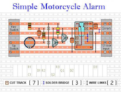
Veroboard Layout


Read More..

Friday, December 20, 2013

10W Audio Amplifier With Bass Boost

High Quality, very simple design, No preamplifier required

This design is based on the 18 Watt Audio Amplifier, and was developed mainly to satisfy the requests of correspondents unable to locate the TLE2141C chip. It uses the widespread NE5532 Dual IC but, obviously, its power output will be comprised in the 9.5 - 11.5W range, as the supply rails cannot exceed ±18V. As amplifiers of this kind are frequently used to drive small loudspeaker cabinets, the bass frequency range is rather sacrificed. Therefore a bass-boost control was inserted in the feedback loop of the amplifier, in order to overcome this problem without quality losses. The bass lift curve can reach a maximum of +16.4dB @ 50Hz. In any case, even when the bass control is rotated fully counterclockwise, the amplifier frequency response shows a gentle raising curve: +0.8dB @ 400Hz, +4.7dB @ 100Hz and +6dB @ 50Hz (referred to 1KHz).

 10W Bass Boost Amplifier Circuit diagram:

10W Audio Amplifier with Bass boost Circuit Diagram
Parts:

P1_________________22K Log.Potentiometer (Dual-gang for stereo)
P2_________________100K Log.Potentiometer (Dual-gang for stereo)
R1_________________820R 1/4W Resistor
R2,R4,R8___________4K7 1/4W Resistors
R3_________________500R 1/2W Trimmer Cermet
R5_________________82K 1/4W Resistor
R6,R7______________47K 1/4W Resistors
R9_________________10R 1/2W Resistor
R10________________R22 4W Resistor (wirewound)
C1,C8______________470nF 63V Polyester Capacitor
C2,C5______________100µF 25V Electrolytic Capacitors
C3,C4______________470µF 25V Electrolytic Capacitors
C6_________________47pF 63V Ceramic or Polystyrene Capacitor
C7_________________10nF 63V Polyester Capacitor
C9_________________100nF 63V Polyester Capacitor
D1_________________1N4148 75V 150mA Diode
IC1_________________NE5532 Low noise Dual Op-amp
Q1_________________BC547B 45V 100mA NPN Transistor
Q2_________________BC557B 45V 100mA PNP Transistor
Q3_________________TIP42A 60V 6A PNP Transistor
Q4_________________TIP41A 60V 6A NPN Transistor
J1__________________RCA audio input socket

Power Supply Circuit diagram:

PSU_For_10W_Audio_Amplifier 
Power supply parts:

R11______________1K5 1/4W Resistor
C10,C11__________4700µF 25V Electrolytic Capacitors
D2_______________100V 4A Diode bridge
D3_______________5mm. Red LED
T1_______________220V Primary, 12 + 12V Secondary 24-30VA Mains transformer
PL1______________Male Mains plug
SW1______________SPST Mains switch

Notes:
  • Can be directly connected to CD players, tuners and tape recorders.
  • Schematic shows left channel only, but C3, C4, IC1 and the power supply are common to both channels.
  • Numbers in parentheses show IC1 right channel pin connections.
  • A log type for P2 will ensure a more linear regulation of bass-boost.
  • Do not exceed 18 + 18V supply.
  • Q3 and Q4 must be mounted on heatsink.
  • D1 must be in thermal contact with Q1.
  • Quiescent current (best measured with an Avo-meter in series with Q3 Emitter) is not critical.
  • Set the volume control to the minimum and R3 to its minimum resistance.
  • Power-on the circuit and adjust R3 to read a current drawing of about 20 to 25mA.
  • Wait about 15 minutes, watch if the current is varying and readjust if necessary.
  • A correct grounding is very important to eliminate hum and ground loops. Connect to the same point the ground sides of J1, P1, C2, C3 &C4. Connect C9 to the output ground.
  • Then connect separately the input and output grounds to the power supply ground.
Technical data:

Output power:
10 Watt RMS into 8 Ohm (1KHz sinewave)
Sensitivity:
115 to 180mV input for 10W output (depending on P2 control position)
Frequency response:
See Comments above
Total harmonic distortion @ 1KHz:
0.1W 0.009% 1W 0.004% 10W 0.005%
Total harmonic distortion @ 100Hz:
0.1W 0.009% 1W 0.007% 10W 0.012%
Total harmonic distortion @ 10KHz:
0.1W 0.056% 1W 0.01% 10W 0.018%
Total harmonic distortion @ 100Hz and full boost:
1W 0.015% 10W 0.03%
Max. bass-boost referred to 1KHz:
400Hz = +5dB; 200Hz = +7.3dB; 100Hz = +12dB; 50Hz = +16.4dB; 30Hz = +13.3dB
Unconditionally stable on capacitive loads

Source :  http://www.ecircuitslab.com/2011/05/10w-audio-amplifier-with-bass-boost.html
Read More..

Tuesday, December 17, 2013

Stepper Motor Circuit with IC 4027


This stepper controller circuit shown here can used to control the unipolar stepper motor,which has 4 coils . The stepper controller circuit can drive for a motor current of up to about 500 mAmp/Winding by suitable heat sinks for the SL-100. directsinks In higher currents power transistors seem 2N3055 can be used as darlington pair along with SL-100. All diodes are used to protect back current the transistor from transients.

Stepper Motor Circuit with IC 4027 Circuit diagram :


Remark. 

  • You may be able to substitute any standard (2N3055) power transistor for Q1-Q4 or get IC type UL to modify for transistor.
  • Every time in move the motor put signal the STEP line is pulsed, the motor moves one step.
  • Switch S1 for changes the motors direction

Read More..

Tuesday, October 8, 2013

12 V AUDIO AMPLIFIER WITH TRANSISTOR ELECTRONIC DIAGRAM

12 V AUDIO AMPLIFIER WITH TRANSISTOR ELECTRONIC DIAGRAM

In use, R9 should be carefully adjusted to provide minimal audible signal cross-over distortion consistent with minimal measured quiescent current consumption; a good compromise is to set the quiescent current at about 10-15 mA.To measure this current, wire a DC current meter temporarily in series with the collector of Q3.

List Component

  • P1_____________10K Log.Potentiometer
  • R1,R2__________33K 1/4W Resistors
  • R3_____________33R 1/4W Resistor
  • R4_____________15K 1/4W Resistor
  • R5,R6___________1K 1/4W Resistors
  • R7____________680R 1/4W Resistor
  • R8____________120R 1/2W Resistor
  • R9____________100R 1/2W Trimmer Cermet
  • C1,C2__________10µF 63V Electrolytic Capacitors
  • C3____________100µF 25V Electrolytic Capacitor
  • C4,C7_________470µF 25V Electrolytic Capacitors
  • C5_____________47pF 63V Ceramic Capacitor
  • C6____________220nF 63V Polyester Capacitor
  • C8___________1000µF 25V Electrolytic Capacitor
  • D1___________1N4148 75V 150mA Diode
  • Q1____________BC560C 45V 100mA PNP Low noise High gain Transistor
  • Q2____________BC337 45V 800mA NPN Transistor
  • Q3____________TIP31A 60V 4A NPN Transistor
  • Q4 ___________TIP32A 60V 4A PNP Transistor
  • SW1___________SPST switch
Read More..

Friday, October 4, 2013

Li Ion DRIVER WITH EXTERNAL PWM DIMMING ELECTRONIC DIAGRAM


Li-Ion DRIVER WITH EXTERNAL PWM DIMMING ELECTRONIC DIAGRAM

This boost converter is quite useful to improve conversion efficiency, reduce output ripple, and the use of small external components. In default, the LED current is set with external sensor resistor Rset, feed back voltage is regulated to 2000 miliVolts. During the operation, the current LED can be controlled using 1-wire digital interface through CTRL pin or with PWM signal that applied to the CTRL pin through the duty cycle. It determines the feedback reference voltage. The device also has a feature of integrated open LED protection that will disable the boost converter, this is to prevent the output from exceeding the absolute maximum ratings during open LED condition.


  • L1: Murata LQH3NPN100NM0
  • C1: Murata GRM188R61A105K
  • C2: Murata GRM188R61E474K
  • D1: ONsemi MBR0540T1
Read More..

Thursday, September 12, 2013

Eridani – 50 MHz ARM Cortex M3 with USB

Eridani is a LM3S3651 based general purpose development board with USB Host/Device/OTG. You can buy one here. This documentation should help you use it effectively. All of the details on how to setup toolchains for this board are filed under getting started.

Eridani – 50 MHz ARM Cortex M3 with USB
Read More..

Wednesday, September 11, 2013

8 Digit 7 Segment LED Display with SPI Interface

The following display features eight 7-segment displays arranged in two rows of four digits. The on-board MAX7219 driver enables you to easily add eight 7-segment LED displays to your project using only 3 I/O pins of microcontroller.


The major advantage of using this board is the time-division multiplexing operations required for continuous refreshing of the display digits are performed by the MAX7219 chip, thereby keeping the microcontroller free for doing other pressing tasks. It is suitable for displaying two variable values simultaneously in a project, such as displaying temperature and humidity, or current and voltage, etc.
Read More..

Tuesday, September 10, 2013

50W DC DC Converters TRACOPOWER with the Highest Power Density

TRACOPOWER launches the high performance TEN50 Series with 12 models providing 50W power in a 1”x 2”x 0.4 “ compact package. Today already almost all of applications require a high efficiency of a voltage conversion. When we add to this requirement also saving of space and a galvanic isolation, we´ll get to widely used components – DC/DC modules. The TEN 50 Series models feature a very high efficiency of up to 92%. Excellent efficiency is maintained in over a wide load range and no minimum load is required for an accurate output regulation. They are available in three basic groups – TEN 50-12xx, TEN 50-24xx a TEN 50-48xx with a wide input voltage range (2:1).

50W DC/DC Converters TRACOPOWER with the Highest Power Density
 
Low thermal losses and the use of highest grade components allow an operating temperature range of –40°C to +85°C while up to 55°C no forced air cooling is required. With an optional heat-sink this temperature can even be increased. An operation without a forced air cooling is possible even at higher temperatures – at an adequate power derating ( 2%/K above 55°C and 2,5%/K above 65°C). The TEN 50 Series comes with remote On/Off function and have an adjustable output voltage (± 10%). Protection against overload and short-circuit, very compact dimensions and a 1500VDC isolation enable usage of TEN 50 modules in virtually any power application.
Read More..

Wednesday, May 29, 2013

Adjustable Switching Regulator Circuit with LM2576

The Adjustable Switching Regulator Circuit with LM2576 are monolithic integrated circuits that provide all the active functions for a step-down (buck) switching regulator, capable of driving 3A load with excellent line and load regulation. These devices are available in fixed output voltages of 3.3V, 5V, 12V, 15V, and an adjustable output version.
LM2576 IC Package
LM2576 IC Package
Requiring a minimum number of external components, these regulators are simple to use and include internal frequency compensation and a fixed-frequency oscillator. The Adjustable Switching Regulator Circuit with LM2576 offers a high-efficiency replacement for popular three-terminal linear regulators. It substantially reduces the size of the heat sink, and in some cases no heat sink is required.


Adjustable Switching Regulator Circuit with LM2576
IC Switching Regulator Circuit with LM2576

A standard Adjustable Switching Regulator Circuit with LM2576 of inductors optimized for use with the LM2576 are available from several different manufacturers. This feature greatly simplifies the design of switch-mode power supplies.

Other features include a guaranteed ±4% tolerance on output voltage within specified input voltages and output load conditions, and ±10% on the oscillator frequency. External shutdown is included, featuring 50 μA (typical) standby current. The output switch includes cycle-by-cycle current limiting, as well as thermal shutdown for full protection under fault conditions.

Features Adjustable Switching Regulator Circuit with LM2576 :
- 3.3V, 5V, 12V, 15V, and adjustable output versions
- Adjustable version output voltage range,1.23V to 37V
- Guaranteed 3A output current
- Wide input voltage range, 40V up to 60V for HV version
- Requires only 4 external components
- 52 kHz fixed frequency internal oscillator
- TTL shutdown capability, low power standby mode
- High efficiency
- Uses readily available standard inductors
- Thermal shutdown and current limit protection
- P+ Product Enhancement tested
Read More..

Sunday, May 26, 2013

LED Flasher For the Christmas With NE555

I know now you are getting ready for your christmas.So I thought to give you a useful circuit.This is a LED flasher circuit .You can use this to decorate your christmas star or your crib.I have used here NE555 commen IC.this circuit works with 9v power supply.
Read More..

Thursday, April 11, 2013

Simple USB player circuit with PCM2902

Usb series player is an electronic device or electronic circuit that functions as an MP3 player that is stored on a storage device such as USB flash.

usb mp3 player


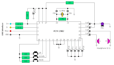
In this usb circuit using an IC as a modifier of digital voice data into analog so that it can be applied to a headphone, or again through the power amlplifier strengthened so that it can be heard through the speakers. IC used in this circuit using IC PCM2902 as a modifier of a digital data into analog data storage.

Below is a schematic diagram of a USB player.
USB mp3 player schematic
Schematic usb player
Read More..

Friday, April 5, 2013

9V DC Adapter With Battery Backup

With just a low cost DC adapter and the circuit described here it is possible to build a low cost stabilized, uninterruptable 9V supply. On the grounds of safety and economy, a simple unstabilized 12V D.C. adapter is used as the power source, a universal adapter with its output set to 12 V will do equally well. The output voltage of an adapter under low load conditions (up to approximately 1/3 of the rated output current) is over 15 V, even at the rated output current, there will be sufficient voltage to supply a 9 V voltage regulator. The rating of the DC adapter should be chosen according to the output current required at 9V. Common values are 300mA, 500mA and 1A.

The 9V voltage regulator used in this circuit has a built in thermal shutdown mechanism so that if too much current is drawn from the device, it simply turns off as it overheats and will not supply any current until the case temperature returns to normal. If the unit is intended to supply more than say 150-200mA then to prevent thermal shutdown it will be necessary to fit a heatsink to the voltage regulator. The rule of thumb used to calculate the size of heatsink is that you should be able to touch it during operation at maximum load, without burning you finger. When choosing the DC adapter, it is always better to select one with a higher current rating than is needed this will ensure that its output voltage is high enough to be able to also charge the 12V cells.

DC Adapter with Battery Backup Circuit DiagramAs long as mains voltage is on the DC adapter, the voltage across C1 will be higher than the voltage of the cells. Charging current will flow through R1 and D1 to the cells. Current also flows to the voltage regulator and out to the load connected at the output. Diode D2 in this situation will not conduct because the voltage at its cathode is greater than that at its anode When the mains voltage fails or is turned off, diode D2 conducts and current will now flow from the Nickel Cadmium cells to the voltage regulator, thereby automatically keeping the output voltage at 9V. The value of resistor R1 is chosen so that a charging current to the cells is not greater than 1/10th of the cells capacity (if the cells are rated at 1100mAh, the charging current must not exceed 110mA).

From the point of view of cell longevity it is better to reduce this charging current even further (1/20 or 1/50 C). When calculating this resistor, the value of the no-load voltage should be used. This will give the highest charging current. To calculate the charging current using R1 with a value of 180 Ω. The cells measure 13.8 V when fully charged and the no-load output voltage of the DC adapter is 17V. Charging current is given by the formula: (17V – 13.8V – 0.7V) / 180 = 13.9mA. Substituting the actual measured values in this formula will enable you to calculate the value of R1 to give the correct charging current for the cells.
Read More..