Showing posts with label led. Show all posts

Tuesday, February 4, 2014

Auto Brightness Adjustment to Seven Segment LED Displays

Raj from Embedded Lab shows in his latest tutorial guide how to implement adaptive brightness control to seven segment LED displays for optimum readability in all illumination conditions. The technique has been demonstrated by constructing a temperature and humidity meter that adapts the brightness of the seven segment LED displays to the surrounding lighting conditions.The project uses a general purpose LDR to sense the surrounding illumination and MAX7219 to drive the LED display.

Implementing Auto-Brightness Adjustment to Seven Segment LED Displays
Read More..

Friday, December 20, 2013

230V Led Flasher Circuit using DIAC

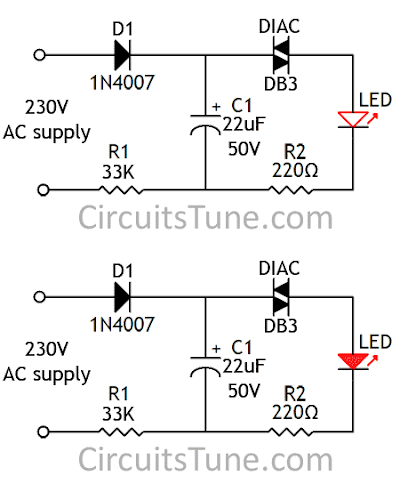
This is a very simple LED flasher circuit diagram that is powered from AC 230V mains. This Flasher can be used as a power indicator for the AC 230V mains supply. This circuit is made with few numbers of parts namely, a LED, two Resistors, one Capacitor, one Diode and one DIAC.  The DIAC act the main role to flashing the LED. DIAC is a bidirectional device. It conducts current only after its breakover voltage has been reached its threshold. Most DIACs break-over voltage is around 30 V.


230V Mains Power Indicator LED Flasher Circuit Diagram


230V Led Flasher
Fig: Circuit Diagram of 230V Led Flasher

When mains is connect to the circuit, the Capacitor(C1) starts charging through Diode(D1) and Resistor(R1). When the voltage on the capacitor reached the DIAC’s threshold voltage, the DIAC get turn on. And LED gets Lights(flash). At the same time Capacitor(C1) goes discharges and breakover voltage of DIAC also decrease and LED turns OFF. The on off time of the LED depends on the value of Capacitor(C1)  and Resistor(R1).
Note that the flashing time of the LED shown in the animating figure is not the exact timing of ON/OFF.
Read More..

Tuesday, October 1, 2013

LED Lighting For Consumer Unit Cupboard

The consumer unit (or ‘electricity meter’) cupboard in some older houses is a badly lit place. If the bell transformer is also located in this cupboard, it may be used to provide emergency lighting by two high-current LEDs. These diodes are powered via a small circuit that switches over to four NiCd batteries when the mains fails. The output voltage of the bell transformer is rectified by bridge B1 and buffered by capacitor C1. The batteries are charged continuously with a current of about 7.5 mA via diode D1 and resistor R2. The base of transistor T1 is high via R3, so that the transistor is cut off. When the mains voltage fails, C1 is discharged via R1; when the potential across it has dropped to a given value, the battery voltage switches on T1 via R3 and R1, provided switch S1 is closed. When T1 is on, a current of some 20 mA flows through diodes D4 and D5. The light from these LEDs is sufficient to enable the defect fuse or the tripped circuit breaker to be located.

Read More..

Dancing LED lights


This is another simple circuit. The whole circuit is mainly operated by four small transistors ( BC 548 x 4 ).  In this circuit diagram we have used twelve LED bulbs. You can use this dancing LED lights for many purpose. If you want you can adjust the dancing speed of the lights.

The supply voltage is 6 Volts as per our recommendation. But you can give up to 7 Volts. When fixing LED lights make sure to consider about the plus and negative sides.  Use different colours of LED lights and we sure you will be enjoyed the final results.


Read More..

Tuesday, September 24, 2013

LED Light Pen

Physicians and repair engineers often use small light pens for visual examination Spurposes. Rugged and expensive as these pens may be, their weak point is the bulb, which is a ‘serviceable’ part. In practice, that nearly always equates to ‘expensive’ and / or ‘impossible to find’ when you need one. LEDs have a much longer life than bulbs and the latest ultra bright white ones also offer higher energy-to-light conversion efficiency. On the down side, LEDs require a small electronic helper circuit called ‘constant-current source’ to get the most out of them. Here, T1 and R1 switch on the LED. R2 acts as a current sensor with T2 shunting off (most of) T1’s base bias current when the voltage developed across R2 exceeds about 0.65 V.

LED Light Pen circuit schematic

The constant current through the white LED is calculated from R2 = 0.65 / I LED With some skill the complete circuit can be built such that its size is equal to an AA battery. The four button cells take the place of the other AA battery that used to be inside the light pen.
Read More..

Wednesday, September 11, 2013

8 Digit 7 Segment LED Display with SPI Interface

The following display features eight 7-segment displays arranged in two rows of four digits. The on-board MAX7219 driver enables you to easily add eight 7-segment LED displays to your project using only 3 I/O pins of microcontroller.


The major advantage of using this board is the time-division multiplexing operations required for continuous refreshing of the display digits are performed by the MAX7219 chip, thereby keeping the microcontroller free for doing other pressing tasks. It is suitable for displaying two variable values simultaneously in a project, such as displaying temperature and humidity, or current and voltage, etc.
Read More..

Sunday, May 26, 2013

LED Flasher For the Christmas With NE555

I know now you are getting ready for your christmas.So I thought to give you a useful circuit.This is a LED flasher circuit .You can use this to decorate your christmas star or your crib.I have used here NE555 commen IC.this circuit works with 9v power supply.
Read More..