Friday, May 31, 2013

Installingreplacing Electrical Outletreceptacle Part

Outlet Wiring Diagram on Installing   Replacing An Electrical Outlet  Receptacle    Part 1
Installing Replacing An Electrical Outlet Receptacle Part 1.


Outlet Wiring Diagram on Wiring In The Home  Switch Conversion  Gfci Receptacle  Wire Nuts
Wiring In The Home Switch Conversion Gfci Receptacle Wire Nuts.


Outlet Wiring Diagram on You Must Test The Outlet When You Complete To Ensure It Is Working
You Must Test The Outlet When You Complete To Ensure It Is Working.


Outlet Wiring Diagram on Half Hot Outlet Wiring Diagram
Half Hot Outlet Wiring Diagram.


Outlet Wiring Diagram on If We Follow This Wall Outlet Circuit Out To A Duplex Wall Outlet It
If We Follow This Wall Outlet Circuit Out To A Duplex Wall Outlet It.


Outlet Wiring Diagram on Figure 7 Shows How An Outlet Shouldbe Wired  Black For Hot  White For
Figure 7 Shows How An Outlet Shouldbe Wired Black For Hot White For.


Outlet Wiring Diagram on Power Coming In At Light With 2 Way Switch And Outlet
Power Coming In At Light With 2 Way Switch And Outlet.


Outlet Wiring Diagram on Illustrates The 1994 Honda Accord Fog Lamps Circuit Wiring Diagram
Illustrates The 1994 Honda Accord Fog Lamps Circuit Wiring Diagram.


Outlet Wiring Diagram on Wiring Diagram Each Hot Wire Will Go Directly To One Of The Outlets
Wiring Diagram Each Hot Wire Will Go Directly To One Of The Outlets.


Outlet Wiring Diagram on Review Of Switched Outlet Wiring  Power Enters At The Outlet
Review Of Switched Outlet Wiring Power Enters At The Outlet.


Read More..

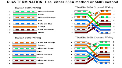
Cable Crossed Cables Note Crossed Wiring

Rj45 Wiring Diagram on Rj45 Wiring 568b
Rj45 Wiring 568b.


Rj45 Wiring Diagram on We Use Red Cable For Crossed Cables Note  All Our Crossed Wiring Is
We Use Red Cable For Crossed Cables Note All Our Crossed Wiring Is.


Rj45 Wiring Diagram on Rj45 Cat6 Wiring Diagram Submited Images Pic 2 Fly
Rj45 Cat6 Wiring Diagram Submited Images Pic 2 Fly.


Rj45 Wiring Diagram on Wiring Diagrams
Wiring Diagrams.


Rj45 Wiring Diagram on Cat5 Socket Wiring Diagram   Reviews And Photos
Cat5 Socket Wiring Diagram Reviews And Photos.


Rj45 Wiring Diagram on How To Make A Rj45 Cable Tester    Rj45 Jack
How To Make A Rj45 Cable Tester Rj45 Jack.


Rj45 Wiring Diagram on Rj45 Wiring Diagram
Rj45 Wiring Diagram.


Rj45 Wiring Diagram on Welcome To Tutor Piggy Blogspot Com  Rj45 Wiring Diagram
Welcome To Tutor Piggy Blogspot Com Rj45 Wiring Diagram.


Rj45 Wiring Diagram on Diagram Of How Rj45 Socket Wiring Shouild Be Terminated Wiring Diagram
Diagram Of How Rj45 Socket Wiring Shouild Be Terminated Wiring Diagram.


Rj45 Wiring Diagram on Order Of The Bath    Churchtech
Order Of The Bath Churchtech.


Read More..

Telephone Wiringclick Image Zoom

Telephone Wiring on Telephone Wiring  Click Image To Zoom
Telephone Wiring Click Image To Zoom.


Telephone Wiring on Lju 2 3a Telephone Extension Socket Telephone Wiring
Lju 2 3a Telephone Extension Socket Telephone Wiring.


Telephone Wiring on Telephone Socket Wiring Diagram
Telephone Socket Wiring Diagram.


Telephone Wiring on Doing Your Own Telephone Wiring
Doing Your Own Telephone Wiring.


Telephone Wiring on Mode 3 Telephone Connector   C Bus Forums
Mode 3 Telephone Connector C Bus Forums.


Telephone Wiring on Check Bt Phone And Broadband Line   Anglesey Computer Solutions Repair
Check Bt Phone And Broadband Line Anglesey Computer Solutions Repair.


Telephone Wiring on Is A Break In A Telephone Wire With Structured House Wiring Methods
Is A Break In A Telephone Wire With Structured House Wiring Methods.


Telephone Wiring on The Wiring Is Pretty Straight Forward Though Colors In The Telephone
The Wiring Is Pretty Straight Forward Though Colors In The Telephone.


Telephone Wiring on Telephone Wiring
Telephone Wiring.


Telephone Wiring on Additional Views Showing Telephone Pinout
Additional Views Showing Telephone Pinout.


Read More..

Thursday, May 30, 2013

Breaktelephone Wire Structured House Wiring Methods

Telephone Wiring on Doing Your Own Telephone Wiring
Doing Your Own Telephone Wiring.


Telephone Wiring on Mode 3 Telephone Connector   C Bus Forums
Mode 3 Telephone Connector C Bus Forums.


Telephone Wiring on Check Bt Phone And Broadband Line   Anglesey Computer Solutions Repair
Check Bt Phone And Broadband Line Anglesey Computer Solutions Repair.


Telephone Wiring on Is A Break In A Telephone Wire With Structured House Wiring Methods
Is A Break In A Telephone Wire With Structured House Wiring Methods.


Telephone Wiring on The Wiring Is Pretty Straight Forward Though Colors In The Telephone
The Wiring Is Pretty Straight Forward Though Colors In The Telephone.


Telephone Wiring on Telephone Wiring
Telephone Wiring.


Telephone Wiring on What You Should Know About Telephone And Rj45 Cat5e Wiring Codes
What You Should Know About Telephone And Rj45 Cat5e Wiring Codes.


Telephone Wiring on Telephone Jack Connection   Group Picture  Image By Tag
Telephone Jack Connection Group Picture Image By Tag.


Telephone Wiring on The R11 On My Interface Charger Board Is Smoking Hot And Is Turning
The R11 On My Interface Charger Board Is Smoking Hot And Is Turning.


Telephone Wiring on Infrastructure Wiring Block Diagram Show Ing
Infrastructure Wiring Block Diagram Show Ing.


Read More..

Wednesday, May 29, 2013

Adjustable Switching Regulator Circuit with LM2576

The Adjustable Switching Regulator Circuit with LM2576 are monolithic integrated circuits that provide all the active functions for a step-down (buck) switching regulator, capable of driving 3A load with excellent line and load regulation. These devices are available in fixed output voltages of 3.3V, 5V, 12V, 15V, and an adjustable output version.
LM2576 IC Package
LM2576 IC Package
Requiring a minimum number of external components, these regulators are simple to use and include internal frequency compensation and a fixed-frequency oscillator. The Adjustable Switching Regulator Circuit with LM2576 offers a high-efficiency replacement for popular three-terminal linear regulators. It substantially reduces the size of the heat sink, and in some cases no heat sink is required.


Adjustable Switching Regulator Circuit with LM2576
IC Switching Regulator Circuit with LM2576

A standard Adjustable Switching Regulator Circuit with LM2576 of inductors optimized for use with the LM2576 are available from several different manufacturers. This feature greatly simplifies the design of switch-mode power supplies.

Other features include a guaranteed ±4% tolerance on output voltage within specified input voltages and output load conditions, and ±10% on the oscillator frequency. External shutdown is included, featuring 50 μA (typical) standby current. The output switch includes cycle-by-cycle current limiting, as well as thermal shutdown for full protection under fault conditions.

Features Adjustable Switching Regulator Circuit with LM2576 :
- 3.3V, 5V, 12V, 15V, and adjustable output versions
- Adjustable version output voltage range,1.23V to 37V
- Guaranteed 3A output current
- Wide input voltage range, 40V up to 60V for HV version
- Requires only 4 external components
- 52 kHz fixed frequency internal oscillator
- TTL shutdown capability, low power standby mode
- High efficiency
- Uses readily available standard inductors
- Thermal shutdown and current limit protection
- P+ Product Enhancement tested
Read More..

Rain Detector Circuit Diagram


This is a Rain detector alarm circuit.You can keep the sensing part out of the house.If water drops fell on the sensing part the alarm will start to ring.so this is very useful circuit for you.Here we have used common IC NE 555.Think and use this in different way..


Read More..

Monday, May 27, 2013

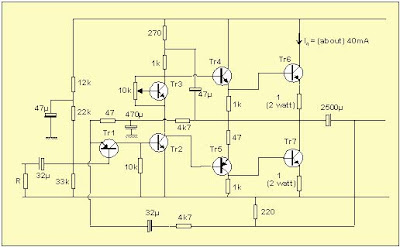
Simple Power Amplifier Circuit [2N3055]

Simple Power Amplifier Circuit Diagram

Simple Power Amplifier Circuit Diagram
Read More..

Sunday, May 26, 2013

LED Flasher For the Christmas With NE555

I know now you are getting ready for your christmas.So I thought to give you a useful circuit.This is a LED flasher circuit .You can use this to decorate your christmas star or your crib.I have used here NE555 commen IC.this circuit works with 9v power supply.
Read More..

Sunday, May 19, 2013

Measuring motor insulation using HI POT tester

What is HI-POT tester?
When we need to evaluate motor condition,HI-POT tester or High Potential tester is the common equipment are used.As we know,a multimeter or ohm meter reading only can determine if a motor winding is open or shorted but cannot checked winding insulation condition if shorted with ground or phase.
The main purpose of the Hi Pot tester is to verify the quality and integrity of the electric motor insulation materials used on the armature or stator and also safe to using it without any defect.
Sometime we not take a serious attention or not know about it to checked winding insulation.This step is important to ensure motor can running in good condition without any breakdown.
Normally electrical motor may have a weakened winding that shorts to ground when it running.It have several caused for the winding breakdown due to the value of system voltage,winding heat build up or overloaded mechanical stress.For other caused it will come from motor terminal board that has an insulation failure from the terminal to ground (earth) or from other terminal for winding connection.

Basic operation of HI-POT Tester
A HI-POT tester produce power source with a high voltage (Volt) and low current (ampere) and it is used to check for an insulation failure for motor winding that the ohmmeter cannot measure with its low voltage power source may miss.
It measures winding insulation resistance to ground (earthing) and terminal board resistance from terminal to ground and from terminal to terminal ( phase to phase )
To get a best result and for safety reason when perform measurement for winding insulation resistance,all wiring is removed from the motor winding terminals.It also same when perform measurement for terminal board resistance, all wiring is removed from the terminal board.
Below is several rules when using the Hi-Pot tester.It is to avoid any serious damage or injuries during insulation measurement and should never be :

1. Operated alone or by an inexperienced service person.
2. Set at a voltage of more than twice the motor operating voltage plus 1000 volts.
3. Be set for more than 5 milliamps without consulting or refer user manual from motor manufacture
4. Applied for more than the time it takes to obtain a reading (no more than a few seconds).
5. Used as a phase-to-phase winding check.
6. For air condition motor compressor,used when the system is in a vacuum.

* SAFETY NOTE : Please read HI-POT tester user manual before using it and refer to the trained or qualified person for assist during measurement.It the best way to avoid any unexpected issued and for safety reason.
Read More..

Pedal Generator Projects


Why pedaling for electricity ?

Know the cost of one KWh as your electricity company sells it ? It's EUR
0.23 in my place and earning this through pedal power would take me 10
hours. Not much of an incentive to think about pedal generators. Still
the need for pedal power generation seems to exist, as frequent e-mail
requests tell me. Well, pedal power can be made available anywhere, it
requires no fuel, is available both day and night, the equipment is
inexpensive and needs almost no maintenance.


This page addresses two key use cases:

  1. Charging batteries for small, portable devices while traveling on a bicycle
  2. Generating as much electrical power as possible on a stationary pedal generator


Low power battery charging


Lo power bicycle battery charger
This project fits a travel bike that will be taken to remote locations
with no electricity. The user will be able to charge NiMH batteries for
light, communication, navigation and entertainment equipment, utilizing
the energy from the bike's standard 6V/3W dynamo. While riding, up to 6W
of electrical power are available to the charger (not a mistake, it is
about twice the rated dynamo power).


A switch selects either the light system,
the battery charge mode or OFF. In charge mode, the rectified dynamo
current is driven through a string of series-connected NiMH cells. At
moderate riding speed, one to 10 cells can be charged at once. The
current is typically 500mA and decreases somewhat as cell count
increases. The ammeter displays the charge current, so it's easy to see
if cells charge correctly and at the expected current.


All 4 diodes are 1N5402 (or 1N5404 through 1N5408). Alternatively, use
1N4003 through 1N4007 (lower current capability, higher chance of damage
if reversing battery polarity).

If individual cells will be charged, an appropriate battery box is
needed. A jumper cable makes the box adapt to fewer cells. It's
acceptable to mix different types of cells; they will all be charged at
the same current.


The circuit withstands operation without batteries connected. Batteries
may remain attached to the circuit permanently, none of the modes
produces a leakage current that discharges the cells. One weak point of
the circuit is wrong battery polarity: This could fry the diodes and the
ammeter. If batteries are likely to be reversed, a fuse should be added
in line with the ammeter.


There is no end-of-charge indication as this would be unreliable with
the fluctuating supply of a dynamo. Not a problem, cells get time to
relax and cool down as the bike stops from time to time. With the rider
being right there with his sense of time and his temperature probe
finger, it's highly unlikely that batteries get forgotten and "cooked"
for many hours. Much unlike cheap mains-powered chargers that overcharge
NiMH cells by design - and still the cells last quite a while.


Stationary pedal generator / high power battery charging


Hub Motor Guts
This project is capable of providing basic electricity to a remote
location where solar panels are not practicable. While pedaling, up to
300W are available (40 ..150 continuously, depending on rider).


The Internet holds a lot of suggestions on how to build a pedal-powered
electrical generator. Now what has put ME off is that all these
solutions require odd parts that are hard to come by and / or demand a
lot of mechanical work in adapting a motor / generator to a bicycle. The
end product often suffers from friction, belt slip and rapid wear.


With the popularity of electric bicycles on the rise, the pedal
generator builder's life has become easier: Today we have a good variety
of bicycle hub motors, many of these made in Chinese factories and
often being sold for less than EUR 100. These motors carry magnets on
the rotor while the copper windings are on the stationary part. They are
perfect dynamos !


Selecting the right motor


  • The motor will be driven on a stationary bike, so has to be a rear
    hub motor (front wheel of stationary bike obviously not being driven)
  • For good efficiency, the motor should employ state-of-the-art rare-earth permanent magnets and it should be brushless
  • To achieve the best flywheel effect, the motor should be heavy and put in a wheel
  • To minimize mechanical losses, the motor should be direct drive / not use internal gears
  • To cope with the power of a physically-fit pedaler for longer
    periods of time, the motor should be rated for at least 200W, more is
    better (reduces losses, increases weight)
  • The voltage of the motor should exceed the desired output voltage,
    so that there's useful output even when not pedaled full-steam

The picture shows the guts of the motor that I've picked. It's a 24V,
500W rear hub motor made by Golden Motor / Jiangsu and it will charge a
12V battery for me.


Hub Motor Generator

The mechanical setup


  1. Find a bicycle to use - it can be any piece of junk but it needs a
    working BB, pedals, chain, a saddle and ideally a rear derailleur
  2. Replace the rear wheel with the hub motor
  3. Put the bike on a stand so that the rear wheel can spin freely (some
    older Durch or Chinese pannier racks incorporate a stand that will work
    nicely). Alternatively suspend the tail of the bike so that it just
    doesn't touch the ground.

    I myself have built a stand from metal brackets mounted on a wooden base.

Restoring the bike to its original condition is fast: Remove from stand and swap the wheel back.


The electrical circuit


Input is the motor / generator on the left of the schematic, output
( 12V-) is on the very right. Any load could be connected to the output:
Light bulbs, fluorescent ballast, LED lighting fixtures, radio, cell
phone charger, TV
Read More..