Showing posts with label car. Show all posts

Thursday, December 19, 2013

Car Boot Light Warning

On many cars, the boot light will not go out until the lid is properly closed. It is all too easy when unloading the car, to leave the lid ajar. If you are unlucky and the car remains unused for some time, the next time you try to start it, the lamp will have drained the battery and you will no doubt utter a few appropriate words. The circuit described here will give a warning of just such a situation.

A mercury tilt switch is mounted in the boot so that as the lid is closed, its contacts close before the lid is completely shut. The supply for the circuit comes from the switched 12 V to the boot lamp and through the mercury switch. When the lid is properly closed, the boot lamp will go out and the supply to the circuit will go to zero. If however the lid is left ajar, the lamp will be on and the mercury switch will close the circuit.

Car Boot  Light  Warning Circuit diagram :


After 5 seconds, the alarm will start to sound, and unless the lid is shut, it will continue for 1 minute to remind you to close the boot properly. The 1-minute operating period will ensure that the alarm does not sound continuously if you are, for example, transporting bulky items and the boot will not fully close. The circuit consists of a dual CMOS timer type 7556 (the bipolar 556 version is unsuitable for this application). When power is applied to the circuit (i.e. the boot lid is ajar) tantalum capacitors C1 and C2 will ensure that the outputs of the timers are high. After approximately 5 seconds, when the voltage across C2 rises to 2/3 of the supply voltage, timer IC1b will be triggered and its output will go low thereby causing the alarm to sound.

Meanwhile the voltage across C1 is rising much more slowly and after approximately 1 minute, it will have reached 2/3 of the supply voltage. IC1a will now trigger and this will reset IC1b. The alarm will be turned off. IC1a will remain in this state until the boot lid is either closed or opened wider at which point C1 and C2 will be discharged through R6 and the circuit will be ready to start again. To calculate the period of the timers use the formula: t = 1.1RC Please note that the capacitor type used in the circuit should be tantalum or electrolytic with a solid electrolyte. The buzzer must be a type suitable for use at D.C. (i.e. one with a built in driver).

Source : www.ecircuitslab.com/2011/.../car-boot-lamp-warning-icm7556.html


Read More..

Friday, September 27, 2013

Car Boot Lamp Warning ICM7556

On many cars, the boot light will not go out until the lid is properly closed. It is all too easy when unloading the car, to leave the lid ajar. If you are unlucky and the car remains unused for some time, the next time you try to start it, the lamp will have drained the battery and you will no doubt utter a few appropriate words. The circuit described here will give a warning of just such a situation. A mercury tilt switch is mounted in the boot so that as the lid is closed, its contacts close before the lid is completely shut. The supply for the circuit comes from the switched 12 V to the boot lamp and through the mercury switch. When the lid is properly closed, the boot lamp will go out and the supply to the circuit will go to zero. If however the lid is left ajar, the lamp will be on and the mercury switch will close the circuit.

Car Boot Lamp Warning Circuit Diagram (ICM7556)After 5 seconds, the alarm will start to sound, and unless the lid is shut, it will continue for 1 minute to remind you to close the boot properly. The 1-minute operating period will ensure that the alarm does not sound continuously if you are, for example, transporting bulky items and the boot will not fully close. The circuit consists of a dual CMOS timer type 7556 (the bipolar 556 version is unsuitable for this application). When power is applied to the circuit (i.e. the boot lid is ajar) tantalum capacitors C1 and C2 will ensure that the outputs of the timers are high. After approximately 5 seconds, when the voltage across C2 rises to 2/3 of the supply voltage, timer IC1b will be triggered and its output will go low thereby causing the alarm to sound.

Meanwhile the voltage across C1 is rising much more slowly and after approximately 1 minute, it will have reached 2/3 of the supply voltage. IC1a will now trigger and this will reset IC1b. The alarm will be turned off. IC1a will remain in this state until the boot lid is either closed or opened wider at which point C1 and C2 will be discharged through R6 and the circuit will be ready to start again. To calculate the period of the timers use the formula: t = 1.1RC Please note that the capacitor type used in the circuit should be tantalum or electrolytic with a solid electrolyte. The buzzer must be a type suitable for use at D.C. (i.e. one with a built in driver).
Read More..

Wednesday, June 12, 2013

Make Your Car Cute And You Have A Happy Travel

Fashionable and elegant objects doom to bring our life so many surprises! Creative circular design is absolutely an aesthetic evolution to us. It is suitable for medium-sized paper towels in major supermarkets. Small volume in the car is also very appropriate! Whats more, its simple design and great volume are practical to our home.

Do you want to get something to protect the Car Hand Gear Knob Lever and keep your hands warm in cold days? This cute and soft Plush Car Hand Gear Knob Lever Cover can make a change for the appearance of your hand gear knob. If you want to get this beautiful and comfortable hand gear knob lever cover, youd better decide soon.

This is an indispensable item for your car. Grasp the opportunity to get one! This elegant Luxury Lace Round Fabric Car Tissue Box with lovely design helps you add more fun to your bath and facilitate the whole coordination of furniture in your bath. The design of the tissue box cover is also welcomed by means of rich characters. Moreover, you can play its role fully in your bed room, car, dining room or more.

It is comfortable to touch and with non-slip design! This Soft Cloth Car Manual Gear Knob Lever Cover can change the appearance of your hand brake. If you want to have a beautiful and comfortable hand brake cover, just take it as a gift for you!


Plush Cloth Bag Cube for Car is easy to use from mobile phones to comment on, and do not worry about hiding in a corner of the cell phone was difficult to find the products work fine, feel good, beautiful, generous, easy to clean.
If you want to get this beautiful and comfortable hand gear knob lever cover, youd better decide soon. It is a warm hand brake cover, soft and delicate touch, and you never worry about the freezing cold in winter while diving. It is easy to hold on to and grip, convenient to use.
Read More..

Wednesday, April 10, 2013

18W Car Stereo Amplifier Rise

This automobile stereo amplifier project is a class AB audio power amplifier using the Hitachi HA13118 module. It not only can be used in automobile application but also in any transportable or home amplifier process. It is simple to construct & has a maximum of outside parts. The module has a high power output from a low voltage supply using the bridge tied load system, & a high gain of 55dB.

This project will be useful in applications where the input signal is a low level, without requiring the use of a separate pre-amplifier. This IC module has a built in surge protection circuit, thermal shutdown circuit, ground fault protection circuit & power supply fault protection circuit making it reliable.
The Specifications of this project 
D.C. Input : 8 – 18V at 1-2 A

Power output : 18W maximum, 4 ohm load, 18V DC supply

S/N ratio : > 70 dB

THD : < 0.2% @ 1W

Freq. Response : ~ 30 Hz to 30 kHz, –3 dB

Input level : < 25 mV, for full output (G > 50dB)

Input Impedance : ~ 30 k ohm

The supply voltage necessary for this project is 8 -18V DC, at least one to two Amps. Maximum output power will only be obtained with a power supply of 18V at greater than two A, using a four ohm speaker. The power supply ought to be well filtered to reduce mains hum, a regulated supply will reduce noise even further. Additional filtering is unnecessary if operating from a battery supply.

Circuit Diagram Description

Most of the circuitry is contained within the amplifier module. C10 is the input coupling capacitor and blocks DC from the input. C11 bypasses any RF which may be present at the input. C1 & C2 provide an AC ground for the inverting inputs of the IC. R1/C7 and R2/C8 provide a high frequency load for stability with difficult speakers. C five & C six provide bootstrap feedback for the IC. C9 & C12 provide power supply filtering.


An externally mounted logarithmic potentiometer of between 10k ohm and 50k ohm, is used depending on the desired input impedance. The impedance ought to be keep as high as feasible for a guitar amp, unless using a separate pre-amp. Make sure-that the heat sink is mounted to the module.


Read More..

Monday, April 8, 2013

Car Mobile Phone Charger Circuit

Car Mobile Phone Charger Circuit
Cellphone battery charging process when were done traveling is a big problem. Because when traveling source of power supply is generally difficult to find. If you turn on your phone then the battery continuously over time will run out within a period of five to six hours and eventually mobile phones unusable. Here is described a series of simple charger that will increase battery life two to three hours.


In principle, the charger uses a series of Limited Voltage Current Source. Generally requires cellphone battery voltage 3.6 - 6 volts DC and currents 180-200 mA to perform the charging process. Cellphone battery usually consists of three NiCd battery cells, and each cell has a voltage of 1.2 volts potential. At the speed - average low flows required to charge mobile phone battery about - about 100mA.

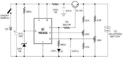
Car Mobile Phone Charger Circuit schematics

In this series there is a 12V voltage source consists of 8 regular battery cells (each cell 1.5 Volt) able to supply current at 1.8 A which is connected with output terminals.

The circuit is also able to monitor the battery voltage level which is in charge. And will automatically cut off the charging process when the output terminal detects a certain battery voltage level predetermined. Timer IC NE555 is used to charge and monitor the voltage level in the battery, Pin 5 (IC1) as the control voltage using a reference voltage zener voltage 5.6Volt. Voltage at Pin 6 as the threshold set by VR1 and the voltage at Pin 2 as the trigger is set by VR2.

When the cellphone battery is connected in series (the Charging Process) applied voltage on PIN2 (IC1) as a trigger would be below the value 1 / 3 Vcc and will cause the Flip-Flop in IC1 will ON and on Pin 3 (IC1) will be high (Cause transistor T1 saturation.). When the battery is full (Full Charge) then the voltage will rise and the voltage on the PIN2 (IC1) will be above the level of trigger point threshold. This will cause the Flip Flop OFF and the output will be low (transistor T1 causes the cutoff) and indirectly also the charging process will stop.

Pin 6 (Threshold IC1) is set at 2 / 3 Vcc by using VR1, transistors T1 which is used to increase the charging current. R3 value is very important to provide the charging current, by setting the value of R3 to 39 ohms then the charging current supplied approximately 180mA. This circuit can be built on any type of PCB (General Purpose PCB) for the calibration process using the DC voltage level cutoff Variable Power Supply. Connect the output terminal circuit with Variable DC Power Supply and set on 7 volts. Adjust VR1 in middle position and slowly adjust VR2 until LED1 OFF, this indicates Low Output. LED1 should turn on when the DC Variable Power Supply voltage is reduced below 5V. LED1 Status flame shown in the table below. Closed circuit with plastic casing and use a suitable connector for connecting to the Battery for Mobile.
Read More..