Showing posts with label charger. Show all posts

Monday, October 7, 2013

Mobile Cellphone Battery Charger

Charging of the cellphone battery is a big problem while travelling as power supply source is not generally accessible. If you keep your cellphone switched on continuously, its battery will go flat within five to six hours, making the cellphone useless. A fully charged battery becomes necessary especially when your distance from the nearest relay station increases. Here’s a simple charger that replenishes the cellphone battery within two to three hours. Basically, the charger is a current-limited voltage source. Generally, cellphone battery packs require 3.6-6V DC and 180-200mA current for charging. These usually contain three NiCd cells, each having 1.2V rating. Current of 100mA is sufficient for charging the cellphone battery at a slow rate. A 12V battery containing eight pen cells gives sufficient current (1.8A) to charge the battery connected across the output terminals.
Circuit Diagram :
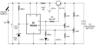
Mobile Cellphone Battery Charger Circuit diagram

The circuit also monitors the voltage level of the battery. It automatically cuts off the charging process when its output terminal voltage increases above the predetermined voltage level. Timer IC NE555 is used to charge and monitor the voltage level in the battery. Control voltage pin 5 of IC1 is provided with a reference voltage of 5.6V by zener diode ZD1. Threshold pin 6 is supplied with a voltage set by VR1 and trigger pin 2 is supplied with a voltage set by VR2. When the discharged cellphone battery is connected to the circuit, the voltage given to trigger pin 2 of IC1 is below 1/3Vcc and hence the flip-flop in the IC is switched on to take output pin 3 high.
Mobile Cellphone Battery Charger
When the battery is fully charged, the output terminal voltage increases the voltage at pin 2 of IC1 above the trigger point threshold. This switches off the flip-flop and the output goes low to terminate the charging process. Threshold pin 6 of IC1 is referenced at 2/3Vcc set by VR1. Transistor T1 is used to enhance the charging current. Value of R3 is critical in providing the required current for charging. With the given value of 39-ohm the charging current is around 180 mA.
The circuit can be constructed on a small general-purpose PCB. For calibration of cut-off voltage level, use a variable DC power source. Connect the output terminals of the circuit to the variable power supply set at 7V. Adjust VR1 in the middle position and slowly adjust VR2 until LED1 goes off, indicating low output. LED1 should turn on when the voltage of the variable power supply reduces below 5V. Enclose the circuit in a small plastic case and use suitable connector for connecting to the cellphone battery.

Note. At EFY lab, the circuit was tested with a Motorola make cellphone battery rated at 3.6V, 320 mAH. In place of 5.6V zener, a 3.3V zener diode was used. The charging current measured was about 200 mA.The status of LED1 is shown in the table.
Author :  Mohan kumar  Copyright : www.efymag.com
Read More..

Tuesday, October 1, 2013

Mobile Phone Battery Charger Circuit Diagram

Small and portable unit, Can be assembled on veroboard

Mobile phone chargers available in the market are quite expensive. The circuit presented here comes as a low-cost alternative to charge mobile telephones/battery packs with a rating of 7.2 volts, such as Nokia 6110/6150.

Circuit diagram:

Mobile_Phone_Battery_Charger_Circuit diagram Mobile Phone Battery Charger Circuit Diagram

Parts Description
R1 1K
R2 47R
R3 10R
R4 47R
C1 1000uF-25V
D1 LEDs any color
D2 LEDs any color
D3 LEDs any color
D4 1N4007
D5 1N4007
Ic1 LM7806
T1 9VAC Xformer 250mA
BR1 Diode bridge 1A
 

Circuit Operation:

The 220-240V AC mains supply is down-converted to 9V AC by transformer T1. The transformer output is rectified by BR1 and the positive DC supply is directly connected to the charger’s output contact, while the negative terminal is connected through current limiting resistor R2. D2 works as a power indicator with R1 serving as the current limiter and D3 indicates the charging status. During the charging period, about 3 volts drop occurs across R2, which turns on D3 through R3.

An external DC supply source (for instance, from a vehicle battery) can also be used to energies the charger, where R4, after polarity protection diode D5, limits the input current to a safe value. The 3-terminal positive voltage regulator LM7806 (IC1) provides a constant voltage output of 7.8V DC since D1 connected between the common terminal (pin 2) and ground rail of IC1 raises the output voltage to 7.8V DC. D1 also serves as a power indicator for the external DC supply. After constructing the circuit on a veroboard, enclose it in a suitable cabinet. A small heat sink is recommended for IC1.

Source :www.extremecircuits.net

Read More..

Tuesday, September 24, 2013

Battery Charger for vehicles


We hope this circuit will help you to understand the action of a Battery charger. Lot of people has no idea how simple it is. In this circuit we have used two diodes, one capacitor and a transformer.  Ammeter is not necessary but it helps us to determine the charging level of the battery.

When you finish the circuit just connect the positive and negative wires to the battery terminals. Make sure to connect the positive wire to the positive terminal of the battery. When the charging is going on you can see 1 to three amps in the ammeter but when the charge is finish or the circuit is disconnected the reading should be zero.

We have used two diodes for full wave rectification and a capacitor is used for DC smoothing. Capacitor is not necessary but we recommend you to use the capacitor always.

The charging time will depend on the size of the transformer, means if we connect a big transformer that means battery gets a higher current ( more than 5A ). Incase if you want to use a higher current transformer use big diodes to pass the current accordingly.


Read More..

Saturday, September 21, 2013

Battery Charger Display Using LT1639

The Over-the-Top type of operational amplifier is ideal for use as a current sense for battery charger applications. The design described here can be used with chargers for rechargeable batteries (Lead/acid or NiCd etc). The 5 V operating supply for the circuit is derived from the battery on charge. The circuit uses a sense resistor R8 to determine the value of current flowing in or out of the battery. An LED output shows whether the battery is charging or discharging and an analogue output displays the battery charge or discharge current. The circuit can also be altered to shown different ranges of charging current to cater for higher capacity cells. IC1a and IC1b together with T1 and T2 form two current sources, which produce a voltage across R5. The voltage across R5 is proportional to the current through resistors R8 and R1 (for IC1a) or R8-R3 (for IC1b).

Battery Charging indicator circuit diagramThe current source formed by IC1a and T1 is active when the batteries are discharging and IC1b and T2 is active when the batteries are being charged. In each case the inactive opamp will have 0V at its output and the corresponding transistor will be switched off. IC1d amplifies the voltage across R5, which is proportional to the sense current. The component values given in the diagram produce an amplification factor or 10. A sense current of 0.1 A will produce an output voltage of +1 V. The supply voltage to the circuit is +5 V so this will be the maximum value that the output can achieve. This corresponds to a maximum charge/discharge current of 0.5 A To display currents from 0 to 5.0 A, resistor R7 can be omitted to give IC1d a voltage gain of 1.

Higher currents can be displayed by using a lower value of sense resistor R8. A DVM or analogue meter can be used at Vout to give a display of the charge/discharge current. The constant current sources can only function correctly when the supply to the voltage regulator circuit (UBatt. e.g. 6V or 12V) is greater than the operating voltage of the opamps (+5 V). The supply voltage to the LT1639 can be in the range of +3 V and +44V and voltages up to 40V over the supply voltage are acceptable at the inputs to the opamp. IC1c controls the charging/discharging LED output. The inputs to this opamp are connected to the outputs of the current source opamps and its output goes high when the battery is being charged and low when it is discharging.
Read More..

Monday, April 8, 2013

9V Automatic Battery NiCd Charger

This automatic NiCd charger for 9V NiCd batteries is using 555 timer properties and is very easy to build. Why is an automatic 9 volts NiCd battery charger? Because you can leave the battery for charging as much as you like: it will be always completely charged and ready for use when is needed. It wont be overcharged and it will not discharge.

9V Automatic Battery NiCd Charger Circuit Diagram :

nicd-charger-circuit-diagram

With the values presented in the circuit diagram, the battery charger NiCd circuit is suitable for 6V and 9V batteries. 9 volt types with 6 and 7 cells are charging with 20mA; P1 must be adjusted so that the NiCd charger disconnects after 14 hours. Window inferior level is set at 1V below this value with P2. 5V battery type with 4 or 5 cells are charged at 55mA. Again, with P1 adjust the NiCd charger circuit so it disconnects after 14 hours. Window inferior level must be set at 0.8V below this value.

Source: http://www.ecircuitslab.com/2012/08/9v-automatic-battery-nicd-charger.html

Read More..

Car Mobile Phone Charger Circuit

Car Mobile Phone Charger Circuit
Cellphone battery charging process when were done traveling is a big problem. Because when traveling source of power supply is generally difficult to find. If you turn on your phone then the battery continuously over time will run out within a period of five to six hours and eventually mobile phones unusable. Here is described a series of simple charger that will increase battery life two to three hours.


In principle, the charger uses a series of Limited Voltage Current Source. Generally requires cellphone battery voltage 3.6 - 6 volts DC and currents 180-200 mA to perform the charging process. Cellphone battery usually consists of three NiCd battery cells, and each cell has a voltage of 1.2 volts potential. At the speed - average low flows required to charge mobile phone battery about - about 100mA.

Car Mobile Phone Charger Circuit schematics

In this series there is a 12V voltage source consists of 8 regular battery cells (each cell 1.5 Volt) able to supply current at 1.8 A which is connected with output terminals.

The circuit is also able to monitor the battery voltage level which is in charge. And will automatically cut off the charging process when the output terminal detects a certain battery voltage level predetermined. Timer IC NE555 is used to charge and monitor the voltage level in the battery, Pin 5 (IC1) as the control voltage using a reference voltage zener voltage 5.6Volt. Voltage at Pin 6 as the threshold set by VR1 and the voltage at Pin 2 as the trigger is set by VR2.

When the cellphone battery is connected in series (the Charging Process) applied voltage on PIN2 (IC1) as a trigger would be below the value 1 / 3 Vcc and will cause the Flip-Flop in IC1 will ON and on Pin 3 (IC1) will be high (Cause transistor T1 saturation.). When the battery is full (Full Charge) then the voltage will rise and the voltage on the PIN2 (IC1) will be above the level of trigger point threshold. This will cause the Flip Flop OFF and the output will be low (transistor T1 causes the cutoff) and indirectly also the charging process will stop.

Pin 6 (Threshold IC1) is set at 2 / 3 Vcc by using VR1, transistors T1 which is used to increase the charging current. R3 value is very important to provide the charging current, by setting the value of R3 to 39 ohms then the charging current supplied approximately 180mA. This circuit can be built on any type of PCB (General Purpose PCB) for the calibration process using the DC voltage level cutoff Variable Power Supply. Connect the output terminal circuit with Variable DC Power Supply and set on 7 volts. Adjust VR1 in middle position and slowly adjust VR2 until LED1 OFF, this indicates Low Output. LED1 should turn on when the DC Variable Power Supply voltage is reduced below 5V. LED1 Status flame shown in the table below. Closed circuit with plastic casing and use a suitable connector for connecting to the Battery for Mobile.
Read More..

Wednesday, April 3, 2013

Li Ion Battery Charger Circuit

The LP2951 regulator is manufactured by National Semiconductors. The choice of values is from an application note "Battery Charging", written by Chester Simpson. Diode D1 can be any diode from the 1N00x series, whichever is conveniently available. It functions as a blocking diode, to prevent a back flow of current from the battery into the LP2951 when the input voltage is disconnected. Charging current is about 100+mA, which is the internally-limited maximum current of the LP2951. For those wondering, this is compatible with just about any single-cell li-ion battery since li-ion can generally accept a charging current of up to about 1c (i.e. charging current in mA equivalent to their capacity in mAh, so a 1100mAh li-ion cell can be charged at up to 1100mA and so on).

Circuit diagram:

Li-Ion Battery Charger Circuit diagram Li-Ion Battery Charger Circuit diagram

A lower charging current just brings about a correspondingly longer charge time. IMHO 100mA is quite low, low enough that the circuit can be used for an overnight charger for many typical single-cell li-ion batteries. The resistors are deliberately kept at large orders of magnitude (tens/hundred Kohm and Mohm range) to keep the off-state current as low as possible, at about 2?A. Resistor tolerances should be kept at 1% for output voltage accuracy. The 50k pot allows for an output voltage range between 4.08V to 4.26V - thus allowing calibration as well as a choice between a charging voltage of 4.1V or 4.2V depending on the cell to be charged. The capacitors are for stability, especially C2 which prevents the output from ringing/oscillating.

Parts
IC1 = LP2951, voltage regulator
D1 = 1N4002, General purpose diode
R1 = 2M, 1%, metal-film
R2 = 806K, 1%, metal-film
P1 = 50K, potentiometer
C1 = 0.1uF, polyester
C2 = 2.2uF/16V, electrolytic
C3 = 330pF, ceramic

Source :www.extremecircuits.net

Read More..

Tuesday, April 2, 2013

Battery Charger Circuit Using Ammeter VU

This is a design of the circuit diagram of a simple and straight forward battery charger that can be used to charge all type of 12V rechargeable batteries including car batteries. This circuit is completed with ammeter VU for displaying the current. This is the figure of the circuit.


The circuit is nothing but a 12V DC power supply with an ammeter for monitoring the charging current. The two diodes forms a centre tapped full wave rectifier. The capacitor filters the rectifier output to produce a clean 12V out put. At initial stages of charging the ammeter will read about 1 to 3 amperes. As the battery is slowly charged the current slowly decreases. For indicate when the battery is fully charged, the ammeter reading will be zero. For attention, it is always be careful to connect the charger to the battery in correct polarity. The polarity is connecting between positive to positive and negative to negative.

Read More..